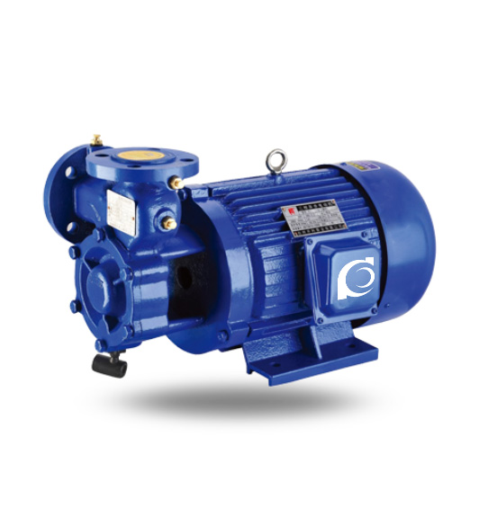
Product Overview
1W Single-Stage Direct-Coupled Vortex Pump is a horizontal direct-coupled single-stage vortex centrifugal pump designed for clean water and water-like liquid transfer in low-flow high-head applications.
It resolves conventional centrifugal pump limitations in delivering relatively clean liquids with varying head requirements while maintaining compact structural form.
It is applied in boiler feed systems, HVAC circulation, irrigation, fire pressure boosting and industrial clear liquid transfer services.
Model Designation

Applications
Typical Operating Conditions
- Boiler feed water supply in small and medium installations
- HVAC chilled/hot water circulation systems
- Agricultural long-distance irrigation transfer
- Building fire pressure boosting and stable supply
- Industrial process clear liquid transfer
Engineering Advantages
Structural Design Logic + Engineering Result
- Direct-coupled single stage vortex structure provides compact installation and simplified power transmission without coupling alignment requirements.
- Peripheral vortex impeller generates a flow field suitable for low-flow, moderate-to-high head performance.
- Large flow area relative to impeller clearance ensures stable operation with minimal hydraulic loss.
- Compact horizontal arrangement reduces footprint and simplifies piping connections.
System Components
1W Single-Stage Direct-Coupled Vortex Pump mainly consists of:
- Pump casing (volute)
- Vortex impeller
- Shaft and bearing assembly
- Direct-coupled motor
- Mechanical seal or packing gland
- Common base frame
Technical Specifications
Service Conditions
• Medium: Clean water or similar liquids with no solids.
Operating Conditions
Based on typical 1W series data from industry references:
- Flow Rate: 1.44 – 14.4 m³/h
- Head: 25 – 120 m
- Power Range: 0.75 – 11 kW
- Speed: 1450 / 2900 rpm
- Liquid Temperature: ≤ 60–80°C
- Working Pressure: ≤ 0.6 MPa
Detailed parameter tables are provided below.
Specifications & Installation
Outline Drawing

Performance Data
| 1 | Motor shaft extension | 9 | Inner partition plate | |
| 2 | Motor | 10 | Pin | |
| 3 | Pump casing | 11 | Inner partition plate | |
| 4 | Shaft collar | 12 | Impeller | |
| 5 | Water-deflector ring | 13 | Coupling shaft | |
| 6 | Key | 14 | Impeller key | |
| 7 | Gland | 15 | Profiled seal ring | |
| 8 | Flexible graphite packing | 16 | Pump cover | |
| The 1W series vortex pump adopts a direct-coupled configuration between pump and motor, with the suction nozzle arranged horizontally and the discharge nozzle vertically upward. Viewed from the pump end, the pump rotates counterclockwise. The impeller can slide freely on the cantilever shaft so that it can automatically adjust the clearance on both sides during operation. The outer partition plate can be removed together with the impeller by means of two threaded holes on the impeller. The impeller and inner partition plate are made of 9-4 aluminum bronze, the shaft is made of stainless steel, and the packing uses a new sealing material — flexible graphite. This design ensures stable performance, simple construction and convenient dismantling. | ||||
Performance Parameters
| Model |
Flow Rate
(m3/h) |
Head
(m) |
Speed
(r/min) |
Power
(kW) |
| 1W2.4-10.5 (single-stage) | 2.4 | 105 | 2900 | 3 |
| 1W2.5-12 (single-stage) | 2.5 | 120 | 2900 | 3 |
| 25W-25 (single-stage) | 1.44 | 25 | 2900 | 0.75 |
| 32W-30 (single-stage) | 2.88 | 30 | 2900 | 1.5 |
| 32W-75 (single-stage) | 2.88 | 75 | 2900 | 4 |
| 40W-40 (single-stage) | 5.4 | 40 | 2900 | 4 |
| 40W-90 (single-stage) | 5.4 | 90 | 2900 | 7.5 |
| 50W-45 (single-stage) | 9 | 45 | 2900 | 5.5 |
| 65W-50 (single-stage) | 14.4 | 50 | 2900 | 11 |
| 1.58D-0.7 (single-stage) | 2.4 | 105 | 1450 | 3 |
How to Select a Pump Model
- Determine required flow and total head based on system resistance.
- Confirm allowable liquid temperature range.
- Evaluate motor power and voltage compatibility.
- Select appropriate sealing method based on leakage tolerance.
Engineering Notes
- Vortex pumps are sensitive to fluid cleanliness; avoid solid particles to maintain performance.
- Direct drive requires shaft alignment and vibration control at installation.
- Efficiency is typically lower than multistage pumps at equivalent head.
- Motor cooling must be adequate at lower flow operating points.
Compliance & Quality Assurance
- Factory hydraulic performance test with flow/head curves.
- Mechanical seal leakage integrity test.
- Material traceability of wetted components.
- Dynamic balance test of impeller and shaft.
Safety Notice
- Do not operate under dry-running condition.
- Ensure suction priming before startup.
- Disconnect power before service.
- Do not operate beyond rated temperature limits.
OEM & Custom
This pump series supports engineered configuration and duty-based matching. Technical adjustments can be made according to system requirements and installation conditions.
Available options include:
• Motor voltage & frequency
• Mechanical seal type and configuration
• Wetted parts material selection
• Surface coating and corrosion protection
Configuration is determined based on duty point and project specifications.
Based on duty point and project specifications.
FAQs
Q: What liquids can the 1W pump handle?
A: Clean water and water-like liquids with no solids.
Q: What is the maximum allowable liquid temperature?
A: Typically ≤ 60–80°C depending on model.
Q: Can it operate under VFD control?
A: Yes, within rated motor limits.
Q: What sealing options are available?
A: Mechanical seal and packing gland.
Q: What is the allowable working pressure?
A: Typically ≤ 0.6 MPa.
Q: Does this pump have self-priming capability?
A: Vortex design offers some self-priming effect; full self-priming depends on suction conditions.
Q: What standards should the pump comply with?
A: Designed per industrial vortex pump and centrifugal pump structural standards.