Product Overview
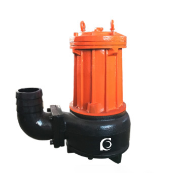
The AS/AV Series Cutting and Grinding Submersible Sewage Pump is designed for wastewater treatment applications involving hard solids, long fibers, and severely contaminated media. This pump integrates cutting, grinding, and conveying functions into a single unit, effectively shredding fibers, plastics, textiles, and similar debris before discharge. It ensures smooth flow and non-clogging operation, providing reliable performance in sewage systems.
Model Designation

Key Features
-
High solids handling capability / anti-clogging: Semi-open three-blade impeller design ensures stable handling of slurry and liquid with solid debris;
-
Cutting and grinding mechanism: Effectively shreds fibers and debris without the need for additional filtration equipment, enabling smooth discharge;
-
Energy-efficient design: Optimized low power consumption for exceptional energy efficiency;
-
Mechanical seal system: Designed for continuous safe operation for over 8000 hours;
-
Compact structure: Small footprint with low operational noise, easy maintenance, and component replacement;
-
Automatic control panel: Automatically starts and stops based on liquid level changes, reducing manual intervention;
-
Dual guide rail automatic coupling system: Facilitates installation and maintenance, with no need to enter sewage pits;
-
Optional fully automatic protection control panel: Provides leakage, inlet, and overload protection for safe operation.
Engineering Summary
The AS/AV Series Cutting and Grinding Submersible Sewage Pump utilizes advanced hydraulic and cutting system designs to ensure efficient operation while handling solids and long fibers. The pump is suitable for applications requiring continuous operation, high energy efficiency, and strong anti-clogging capabilities, including sewage treatment, wastewater handling, and industrial processes that involve fibers and solid materials.
Typical Applications
The AS/AV Series Cutting and Grinding Submersible Sewage Pump is suitable for:
-
Severe wastewater discharge in industrial and commercial facilities
-
Municipal wastewater treatment plant discharge systems
-
Residential sewage pumping stations
-
Civil defense and emergency drainage systems
-
Sewage discharge systems in hospitals, hotels, and public buildings
-
Municipal engineering projects and construction site drainage
-
Auxiliary drainage for mining operations
-
Rural biogas pits and agricultural irrigation systems
It is designed for pumping wastewater containing solid particles, sludge, fibers, and other suspended solids, and is also suitable for clean water or mildly corrosive fluids.
System & Operation
Components & Supply
-
Single-channel or double-channel impeller design: Effectively handles solid particles and fibrous materials, improving non-clogging performance;
-
Wear-resistant mechanical seals: Ensure reliable operation and long service life;
-
Compact structure: Small footprint with low noise, facilitating easy installation and maintenance;
-
Optional automatic control panel: Automates start/stop based on liquid level changes, reducing manual intervention.
Technical Specifications
Operating Conditions
-
Liquid Temperature:
• Standard Pump: ≤ 40°C
• Hot Water Pump: ≤ 80°C (special applications can meet up to 120°C) -
Ambient Temperature: ≤ +40°C
-
Maximum Working Pressure: 10 bar
-
Maximum Allowable Inlet Pressure: Limited by system working pressure
-
Fluid Requirements:
• Clean, low-viscosity, non-flammable, sulfur-free liquids, free from solid particles or fibers
• Suitable for pumping mineral water, softened water, purified water, light oils, and mild chemical fluids
• If the liquid’s density or viscosity exceeds that of water, a higher-rated motor should be selected
• The pump’s suitability for specific liquids depends on factors such as chloride content, pH, temperature, and solvent/oil content
Service Conditions
-
Installation Altitude: Must not exceed 1000 meters; for higher elevation applications, specify at the time of order for proper configuration.
-
The pump must not be used in flammable or explosive environments, nor should it handle combustible liquids.
-
Installation should be in a well-ventilated, dry, and vibration-free location.
-
Maximum ambient temperature should not exceed +40°C.
Protection Functions
-
The motor should be equipped with overload protection, phase failure protection, and overheat protection devices to prevent damage under abnormal conditions.
-
Dry-run protection is recommended to prevent mechanical seal failure in case of insufficient water supply.
-
Pressure switches or variable frequency drives (VFDs) should be used to maintain safe pressure ranges.
-
Check valves and anti-backflow devices must be installed to prevent damage caused by reverse flow after shutdown.
Selection Criteria
-
Select the pump model and number of stages based on required flow rate and head.
-
Choose appropriate wetted materials (e.g., SS304, SS316L) based on fluid temperature, pH, and chloride content.
-
Select sealing structure (mechanical seal or packing seal) based on the fluid’s corrosive properties.
-
Ensure installation space and piping layout compatibility with the horizontal configuration.
-
If the pumped liquid has higher viscosity or density than water, a higher-rated motor should be selected to meet the required shaft power.
Installation & Dimensions
Performance Parameters
| Model |
Flow Rate (m³/h)
|
Head (m)
|
Motor Power (kW)
|
Speed (rpm)
|
Rated Voltage
|
Rated Current
|
Recommended Hose Inner Diameter
|
Auto-Coupling System
|
Weight (kg)
|
|
(m3/h)
|
(M)
|
(kw)
|
(r/min)
|
(V)
|
(A)
|
mm
|
|||
|
AS10-2W/CB
|
15
|
4
|
1.1
|
2850
|
220
|
5.65
|
76
|
80GAK
|
30
|
|
AS10-2CB
|
15
|
4.5
|
1.1
|
2850
|
380
|
2.9
|
76
|
80GAK
|
30
|
|
AS16-2CB
|
29
|
7.6
|
1.5
|
2850
|
380
|
3.5
|
76
|
80GAK
|
33
|
|
AS30-2CB
|
42
|
11
|
3
|
2850
|
380
|
6.4
|
76
|
80GAK
|
40
|
|
AS55-2CB
|
45
|
13
|
5.5
|
2900
|
380
|
11.1
|
127
|
100GAK
|
165
|
|
AS55-4CB
|
100
|
7.5
|
5.5
|
1450
|
380
|
11.6
|
152
|
150GAK
|
180
|
|
AS75-2CB
|
60
|
18
|
7.5
|
2900
|
380
|
15.0
|
127
|
100GAK
|
185
|
|
AS75-4CB
|
145
|
10
|
7.5
|
1450
|
380
|
15.4
|
152
|
150GAK
|
200
|
|
AV14-4
|
22
|
5.8
|
1.5
|
1450
|
380
|
3.5
|
76
|
80GAK
|
33
|
|
AV55-2
|
30
|
20
|
5.5
|
2900
|
380
|
11.1
|
76
|
100GAK
|
165
|
|
AV75-2
|
30
|
25
|
7.5
|
2900
|
380
|
15.0
|
76
|
100GAK
|
200
|
Performance Curves

Installation Diagram

Performance Data
|
Model
|
D
|
F
|
G
|
H
|
J
|
K
|
L
|
M
|
N
|
|
AS10-2W/CB
|
76
|
280
|
220
|
110
|
130
|
70
|
100
|
210
|
373
|
|
AS10-2CB
|
76
|
280
|
220
|
110
|
130
|
70
|
100
|
210
|
373
|
|
AS16-2CB
|
76
|
280
|
220
|
110
|
130
|
70
|
100
|
210
|
373
|
|
AS30-2CB
|
76
|
335
|
220
|
110
|
155
|
70
|
100
|
260
|
398
|
|
AS55-2CB
|
127
|
630
|
350
|
175
|
240
|
160
|
310
|
430
|
688
|
|
AS55-4CB
|
127
|
630
|
350
|
175
|
240
|
160
|
310
|
430
|
688
|
|
AS75-2CB
|
152
|
655
|
400
|
205
|
248
|
190
|
335
|
430
|
740
|
|
AS75-4CB
|
152
|
655
|
400
|
205
|
248
|
190
|
335
|
430
|
740
|
Operating Manual
Usage Instructions
-
Power Supply Inspection & Grounding
(1) Before use, check the insulation resistance of the motor stator windings to ground using a megohmmeter. The resistance value should not be less than 50 MΩ.
(2) Inspect the power cable for any damage, such as cuts or wear. If any damage is found, replace the cable immediately to prevent electrical leakage. Ensure that the cable cross-section matches the current requirements.
(3) If the voltage exceeds ±10% of the rated voltage, do not start the pump.
(4) The grounding wire in the power cable must be properly grounded to prevent electric shock accidents.
Operation & Usage
-
Pump Usage and Safety Inspection
(5) When the pump is submerged in water, it should be lifted vertically. Do not place it horizontally or allow it to sink into the mud. After use, the pump should be lifted, cleaned, and stored in a dry place to prevent freezing.
(6) Never use the power cable as a lifting rope.
(7) Check the rotor’s rotation direction; it should rotate clockwise when viewed from the top of the pump.
(8) The outdoor power switch or terminal should be protected from rain and moisture. Never touch the switch with wet hands or bare feet to prevent electric shock.
Shutdown & Maintenance
-
Shutdown and Maintenance Requirements
(9) Always disconnect the power supply before moving the pump. Do not touch the water source while operating the pump to avoid electrical accidents.
(10) Never operate the motor without one phase connected. If a fuse blows, check the circuit before continuing. Never arbitrarily increase the fuse size.
(11) During pump operation, assign a dedicated operator. If any abnormalities occur, stop the pump immediately and investigate the cause.
(12) After approximately 1250 hours of operation, perform regular maintenance by disassembling the pump seat to check the bearings and sealing condition, clean and replace grease, and replace oil seals, shaft sleeves, and other parts if necessary.
Operation & Troubleshooting
-
Troubleshooting and Maintenance Instructions
(13) When pumping high-sand content liquids, the load will decrease. However, do not modify the pump structure to increase the load.
(14) For pumps with mechanical seals, perform regular maintenance every 3500 hours of operation.
(15) If the pump is out of service for a long period, remove the volute casing, wipe all parts dry, apply a thin layer of anti-rust oil to the moving surfaces, and store the pump in a dry place for future use.
OEM & Custom
OEM/ODM support includes customized voltage/frequency, cable specification, impeller and tearing-mechanism configuration, seal and bearing brands, paint and nameplate, packaging and documentation (test reports, CoC), and guide-rail auto-coupling bases and control boxes tailored to project standards.
FAQs
- Can it handle long fibers and cloth? Yes—built-in tearing mechanism cuts and ejects fibers, bags and cloth to prevent blockage.
- What solid size can pass? Approx. φ30–φ80 mm depending on the model.
- Is automatic start/stop available? Yes—configure a float switch for water-level control.
- How to install for easy maintenance? Use the double guide-rail auto-coupling system to lift/return the pump without entering the pit.
- What protections are in the control box? Leakage lockout, overload, phase-loss and short-circuit protection plus thermal sensor response.
- Service interval? Check/clean regularly; adjust impeller gap to 0.3–0.5 mm; replace oil annually.
- Do you support OEM branding/specs? Yes—branding, voltage/frequency, seals, materials, rail base and control box can be customized.