Article Content
BZ Self-Priming Centrifugal Pump
Professional Installation & Commissioning Technical Guide
Executive Summary
The BZ series self-priming centrifugal pump represents advanced hydraulic engineering designed for reliable water transfer without the need for foot valves or manual priming. This comprehensive technical guide provides installation engineers with detailed procedures, critical tolerances, and commissioning protocols to ensure optimal performance and extended service life. Proper installation is fundamental to achieving the designed efficiency of 45-70% and preventing premature component failure.
1. Technical Overview and Design Philosophy
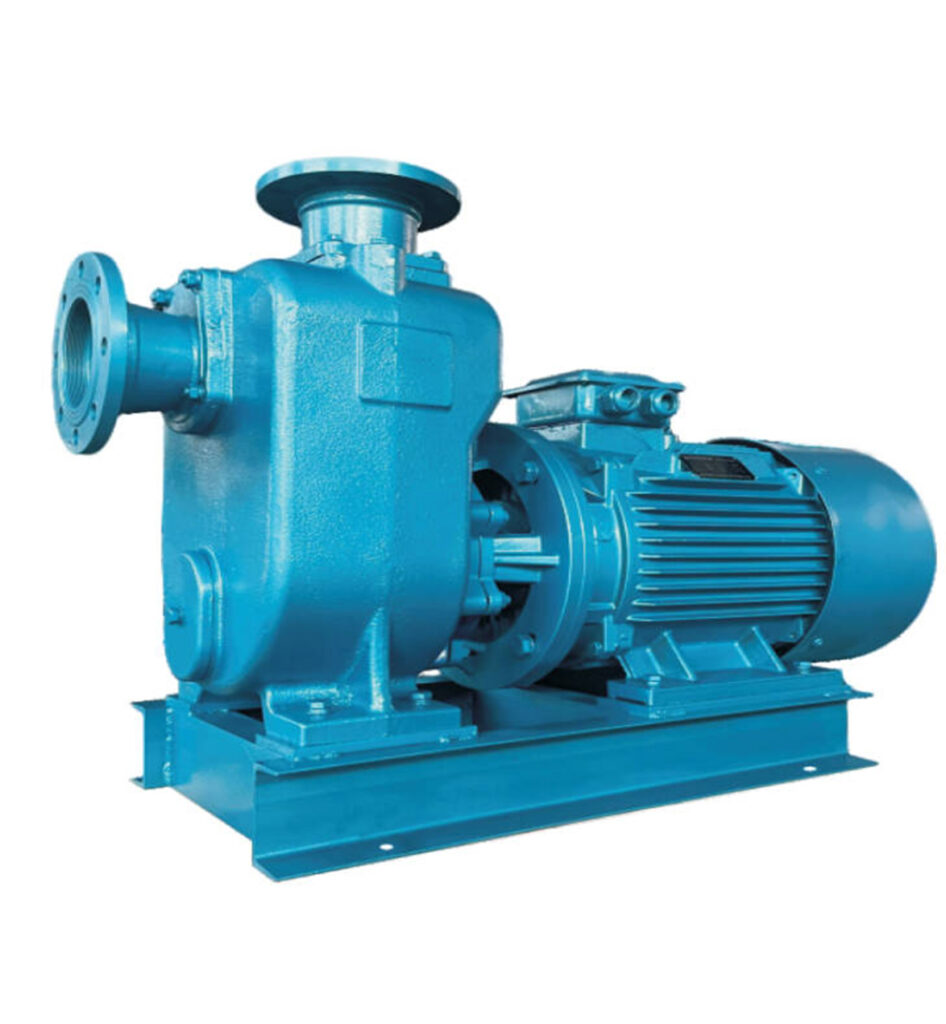
The BZ pump integrates multiple functional components into a compact assembly: the impeller, mechanical seal, gas-liquid separator, and mounting base. This integrated design eliminates traditional priming complexities while maintaining strong suction capability up to 5 meters vertical lift. The hydraulic design employs optimized impeller geometry and volute casing to minimize turbulence and maximize energy transfer efficiency.

Figure 1: BZ Series Self-Priming Centrifugal Pump – Overall Structure and Main Components
1.1 Key Design Features
The self-priming mechanism operates through a sophisticated gas-liquid separation process. During initial startup, the pump chamber retains a predetermined volume of liquid. As the impeller rotates at 1450-2900 r/min, air entrained in the suction line mixes with this retained liquid, forming a gas-liquid emulsion. This mixture is expelled through the discharge port where the gas-liquid separator facilitates air release while returning liquid to the impeller chamber. This cyclic process continues until complete evacuation of air from the suction line, establishing full prime automatically.
1.2 Performance Envelope
| Parameter | Operating Range | Design Point |
|---|---|---|
| Flow Rate | 3 – 400 m³/h | Based on model selection |
| Total Head | 8 – 50 m | Optimized at BEP |
| Motor Power | 0.75 – 90 kW | Matched to duty point |
| Rotational Speed | 1450 / 2900 r/min | Based on motor poles |
| Overall Efficiency | 45 – 70% | Peak at BEP |
| NPSH Required | 3.0 – 5.5 m | At rated flow |
2. Pre-Installation Engineering Assessment
2.1 Site Survey Requirements
Before installation commences, a comprehensive site assessment must be conducted. The foundation must support static pump weight plus dynamic loads during operation without deflection exceeding 0.1mm. Ambient conditions should remain within -10°C to +40°C with adequate ventilation for motor cooling. Minimum clearance of 1.0 meter around all pump sides is required for maintenance access.
2.2 Foundation Specification
The concrete foundation shall be minimum 150mm thickness with compressive strength ≥25 MPa. Anchor bolt embedment depth must be 10-15 times bolt diameter. Surface flatness tolerance is 2mm per meter with total deviation not exceeding 5mm across the entire base plate. Install vibration isolation pads when pump operates near sensitive equipment or structures.
3. Mechanical Installation Procedures
3.1 Base Plate Leveling
Position the base plate on prepared foundation using precision leveling instruments. Achieve levelness tolerance of 0.1mm/m in both longitudinal and transverse directions. Use stainless steel shims for fine adjustment – never use more than 3 shims per location. Once leveled, mark anchor bolt positions, drill holes, clean thoroughly, and install chemical anchors per manufacturer specifications. Allow full cure time (typically 24-48 hours) before proceeding.
3.2 Pump-Motor Alignment
Proper shaft alignment is critical for bearing life and seal performance. Using dial indicators, measure parallel misalignment at coupling hub – acceptable tolerance is ≤0.05mm. Measure angular misalignment using feeler gauges at four quadrants – tolerance is ≤0.05mm/m. Perform alignment at operating temperature when possible, or apply thermal growth compensation calculations for high-temperature applications.
3.3 Piping Connection Guidelines
Suction piping requires special attention to prevent air accumulation. Install piping with continuous upward slope toward pump inlet (minimum 1% grade). Use eccentric reducers with flat top orientation to eliminate air pockets. Maximum recommended suction pipe length is 5 meters with minimum 3 pipe diameters straight run before pump inlet. All joints must be absolutely airtight – apply thread sealant compatible with pumped liquid and torque to specification.

Figure 2: Recommended Suction and Discharge Piping Configuration with Valve Arrangement
4. Electrical Installation and Protection
4.1 Motor Connection
Verify supply voltage matches motor nameplate rating (standard 380V/50Hz/3-phase). Cable sizing must account for full load current plus 25% safety margin. Install motor protection including: thermal overload relay set at 105-110% FLA, short-circuit protection via circuit breaker or fuses, and phase failure protection. Grounding conductor must be minimum 16mm² copper with ground resistance ≤4Ω.
4.2 Rotation Verification
Before coupling installation, perform bump test to verify correct rotation direction. Viewed from motor end, rotation must be clockwise. Incorrect rotation will cause immediate damage to pump hydraulics and seals. If rotation is reversed, interchange any two power leads at the motor terminal box.
5. Commissioning and Performance Verification
5.1 Pre-Start Checklist
Complete systematic verification before energizing: confirm foundation bolts torqued to specification, verify alignment within tolerance, ensure bearing housing filled with correct grease (lithium complex EP2), fill pump chamber to 2/3 capacity with clean water, confirm suction valve fully open and discharge valve 25% open, verify all instrumentation calibrated and functional.
5.2 Initial Start Procedure
Energize motor and immediately verify rotation direction. Monitor start-up current – should peak then settle to running current within 5 seconds. Gradually open discharge valve while monitoring: discharge pressure (should match performance curve), motor current (must not exceed nameplate FLA), bearing temperature (stabilize below 75°C), vibration levels (≤4.5 mm/s RMS), and mechanical seal leakage (acceptable <3 drops/minute).
5.3 Performance Testing
At steady-state operation, record: suction pressure, discharge pressure, flow rate (via flow meter), motor power consumption, and bearing temperatures. Calculate total head and compare with manufacturer performance curve – deviation should be within ±5%. Document all readings in commissioning report for future reference and warranty purposes.
6. Common Installation Errors and Prevention
Critical Mistakes to Avoid:
- Insufficient Foundation: Causes excessive vibration leading to bearing failure
- Poor Alignment: Reduces bearing and seal life by 50-70%
- Air Leaks in Suction: Prevents priming and causes cavitation damage
- Unsupported Piping: Transfers stress to pump casing causing cracks
- Dry Running: Destroys mechanical seals within seconds
7. Documentation and Handover
Complete installation documentation package must include: foundation drawing with as-built dimensions, alignment measurement records, electrical single-line diagram, commissioning test reports, lubrication schedule, and recommended spare parts list. Provide operations and maintenance training to site personnel before project handover.
8. Technical Support and Warranty
Shanghai Chaodun Machinery Manufacturing Group Co., Ltd. provides comprehensive technical support for all BZ series pumps. Standard warranty covers 12 months from commissioning or 18 months from shipment. Extended warranty and service contracts available upon request.
Website: https://cd-pump.com
Technical Support: Available 24/7 for emergency assistance