Product Overview
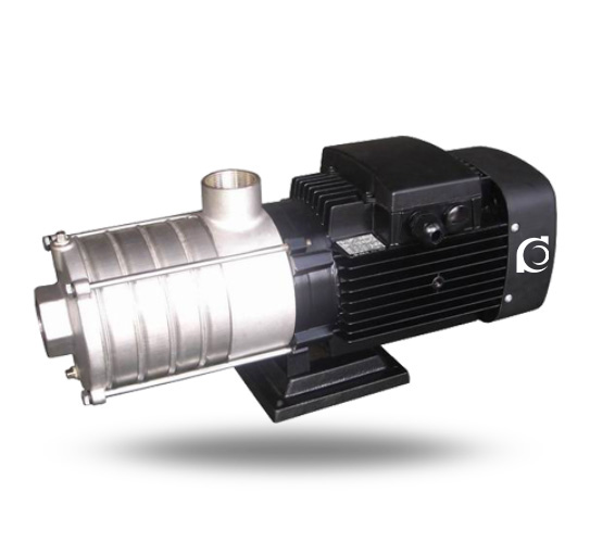
CHDF Stainless Steel Horizontal Multistage Centrifugal Pump is a horizontal stainless steel multistage centrifugal pump designed for high-head clean water and mildly corrosive liquid transfer.
It addresses insufficient pressure in single-stage systems and compensates for pressure loss in long pipelines or multi-floor installations.
It is applied in water treatment units, HVAC circulation systems, industrial process water supply, and high-rise building booster systems.
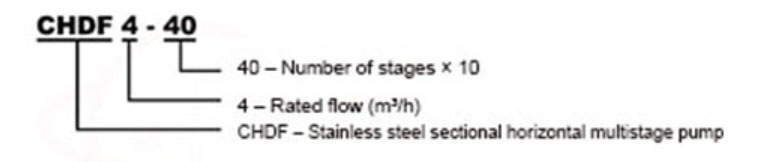
Model Designation
Applications
- High-rise building constant-pressure water supply systems
- Reverse osmosis (RO) water treatment pre-boosting
- Industrial process water circulation and filtration systems
- HVAC chilled and hot water circulation loops
- Cleaning systems and equipment flushing lines
Engineering Advantages
- Horizontal multistage stainless steel hydraulic structure ensures stable axial alignment and predictable performance curve.
- Stainless steel wetted parts provide corrosion resistance for clean and mildly aggressive media.
- Sectional stage configuration allows pressure build-up through impeller stacking for controlled head generation.
- Mechanical seal configuration supports continuous-duty operation with reduced leakage risk.
System Components
The CHDF Stainless Steel Horizontal Multistage Centrifugal Pump mainly consists of:
- Pump casing (stainless steel sections)
- Multistage impellers
- Diffusers
- Pump shaft
- Mechanical seal assembly
- Bearing housing and deep groove ball bearings
- Motor coupling
Technical Specifications
Service Conditions
- Suitable for clean water or liquids with similar physical and chemical properties
- Ambient temperature: ≤ 40°C
- Relative humidity: ≤ 95%
Operating Conditions
- Flow rate: 0.5–22 m³/h
- Head: 5.5–55 m
- Power range: 0.37–4 kW
- Speed: 2900 rpm
- Liquid temperature: ≤ 80°C
- Working pressure: ≤ 1.0 MPa
Detailed parameter tables are provided below.
Installation & Dimensions
Outline Drawing
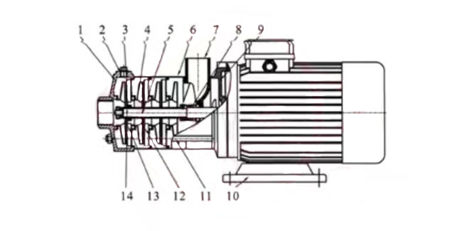
Pump Parts & Materials List
| Item No. | Name | Material | AISI/ASTM | Item No. | Name | Material | AISI/ASTM |
| 1 | Suction Casing | Stainless Steel | AISI304 | 8 | Mechanical Seal | ||
| 2 | End Cover | Stainless Steel | AISI304 | 9 | Motor End Cover | Aluminum Alloy | |
| 3 | Bearing | Tungsten Carbide | 10 | Base | Cast Iron | ASTM258 | |
| 4 | Impeller | Stainless Steel | AISI304 | 11 | Tie Rod | Stainless Steel | AISI304 |
| 5 | Shaft | Stainless Steel | AISI304 | 12 | Diffuser | Stainless Steel | AISI304 |
| 6 | Discharge Diffuser | Stainless Steel | AISI304 | 13 | Support Diffuser | Stainless Steel | AISI304 |
| 7 | Discharge Casing | Stainless Steel | AISI304 | 14 | Impeller Spacer Sleeve | Stainless Steel | AISI304 |
Performance Data
| Model | Motor N (KW) | Flow Rate Q (m3/h) | 0.5 | 1.0 | 1.5 | 2.0 | 2.5 | 3.0 | 3.5 |
| CHDF2-20 | 0.37 | Head H (m) | 19 | 18 | 16 | 14 | 13 | 11 | 9 |
| CHDF2-30 | 0.55 | Head H (m) | 28 | 27 | 24 | 21 | 20 | 17 | 14 |
| CHDF2-40 | 0.55 | Head H (m) | 36 | 34 | 32 | 28 | 26 | 23 | 17 |
| CHDF2-50 | 0.55 | Head H (m) | 46 | 43 | 40 | 35 | 33 | 28 | 22 |
| CHDF2-60 | 0.75 | Head H (m) | 54 | 50 | 48 | 42 | 38 | 33 | 25 |
| Model | Motor N (KW) | Flow Rate Q (m3/h) | 1 | 2 | 3 | 4 | 5 | 6 | 7 |
| CHDF4-20 | 0.55 | Head H (m) | 19 | 18 | 16 | 15 | 13 | 10 | 7 |
| CHDF4-30 | 0.55 | Head H (m) | 28 | 27 | 24 | 22 | 19 | 15 | 10 |
| CHDF4-40 | 0.75 | Head H (m) | 38 | 36 | 32 | 30 | 26 | 20 | 14 |
| CHDF4-50 | 1.1 | Head H (m) | 46 | 44 | 41 | 38 | 32 | 26 | 20 |
| CHDF4-60 | 1.1 | Head H (m) | 55 | 53 | 50 | 45 | 37 | 31 | 26 |
| Model | Motor N (KW) | Flow Rate Q (m3/h) | 5 | 6 | 7 | 8 | 9 | 10 | 11 |
| CHDF8-10 | 0.75 | Head H (m) | 9.5 | 9.3 | 9 | 8.5 | 7.5 | 6.5 | 5.5 |
| CHDF8-20 | 0.75 | Head H (m) | 19 | 18.5 | 18 | 17 | 15 | 13 | 11 |
| CHDF8-30 | 1.1 | Head H (m) | 29 | 28 | 27 | 25.5 | 22.5 | 20 | 17.5 |
| CHDF8-40 | 1.5 | Head H (m) | 39 | 38 | 36 | 34 | 30 | 26.5 | 22.5 |
| CHDF8-50 | 2.2 | Head H (m) | 49 | 47 | 45 | 42.5 | 38 | 33.5 | 28 |
| Model | Motor N (KW) | Flow Rate Q (m3/h) | 10 | 12 | 14 | 16 | 18 | 20 | 22 |
| CHDF16-10 | 1.1 | Head H (m) | 12 | 11.5 | 10.5 | 10 | 9 | 7.5 | 6.5 |
| CHDF16-20 | 2.2 | Head H (m) | 24 | 23 | 22 | 21 | 19 | 17 | 14.5 |
| CHDF16-30 | 3 | Head H (m) | 37 | 36 | 34 | 32 | 30 | 27 | 23 |
| CHDF16-40 | 4 | Head H (m) | 50.5 | 49 | 46 | 43 | 40.5 | 36 | 31.5 |
Installation Diagram
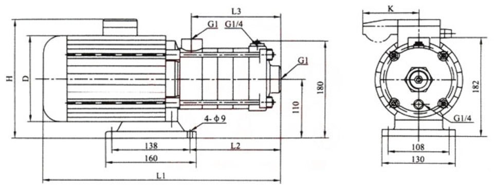
| Model | Motor | L1(mm) | L2(mm) | L3(mm) | D(mm) | H(mm) | K(mm) | Weight (kg) |
| CHDF2-20 | Single-phase | 305 | 87 | 84 | 145 | 215/230 | /96 | 15 |
| CHDF2-30 | Single-phase | 323 | 105 | 102 | 145 | 215/230 | /96 | 15 |
| CHDF2-40 | Single-phase | 341 | 123 | 120 | 145 | 215/230 | /96 | 15 |
| CHDF2-50 | Single-phase | 359 | 141 | 138 | 145 | 215/230 | /96 | 15 |
| CHDF2-60 | Single-phase | 422 | 159 | 156 | 170 | 225/245 | /100 | 17 |
Installation Diagram(2)
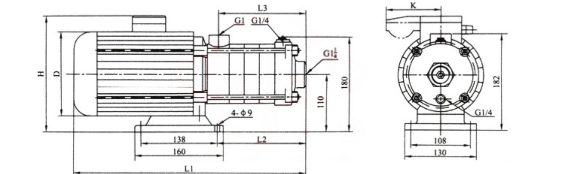
| Model | Motor | L1(mm) | L2(mm) | L3(mm) | D(mm) | H(mm) | K(mm) | Weight (kg) |
| CHDF4-20 | Single-phase | 329 | 105 | 102 | 145 | 215/230 | /96 | 15 |
| CHDF4-30 | Single-phase | 356 | 132 | 129 | 145 | 215/230 | /96 | 15 |
| CHDF4-40 | Single-phase | 416 | 162 | 156 | 170 | 225/245 | /100 | 17 |
| CHDF4-50 | Single-phase | 455 | 188 | 183 | 170 | 225/245 | /100 | 17 |
| CHDF4-60 | Single-phase | 482 | 213 | 210 | 170 | 225/245 | /100 | 17 |
Installation Diagram(3)
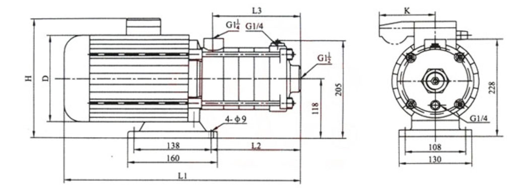
| Model | Motor | L1(mm) | L2(mm) | L3(mm) | D(mm) | H(mm) | K(mm) | Weight (kg) |
| CHDF8-10 | Single-phase | 395 | 126 | 108 | 170 | 230/252 | /100 | 20 |
| CHDF8-20 | Single-phase | 395 | 126 | 108 | 170 | 230/252 | /100 | 20 |
| CHDF8-30 | Single-phase | 425 | 156 | 138 | 170 | 230/252 | /100 | 25 |
| CHDF8-40 | Single-phase | 490 | 186 | 168 | 180 | 240/260 | /100 | 28 |
| CHDF8-50 | Single-phase | 520 | 216 | 198 | 180 | 240/260 | /100 | 30 |
Installation Diagram(4)
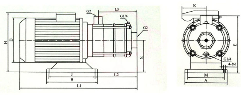
| Model | Motor | L1 | L2 | L3 | H | D | E | N | A | M | B | j | d | k | Weight (kg) |
| CHDF16-10 | Single-phase | 423 | 151 | 126 | 230/265 | 180 | 227 | 117 | 130 | 108 | 160 | 138 | 9 | /100 | 17.5 |
| CHDF16-20 | Single-phase | 455 | 151 | 126 | 240/270 | 180 | 228 | 118 | 130 | 108 | 160 | 138 | 9 | /100 | 27 |
| CHDF16-30 | Single-phase | 561 | 196 | 171 | 270/ | 195 | 240 | 130 | 130 | 108 | 160 | 138 | 9 | 33 | |
| CHDF16-40 | Single-phase | 621 | 339 | 216 | 270/ | 220 | 230 | 120 | 230 | 109 | 190 | 140 | 12 | 41 | |
How to Select a Pump Model
- Determine required flow rate and total dynamic head to ensure duty point falls within high-efficiency region.
- Confirm liquid temperature and material compatibility with stainless steel configuration.
- Evaluate inlet pressure conditions to avoid cavitation.
- Consider installation layout (horizontal footprint and motor power supply).
Engineering Notes
- The pump is non-self-priming and requires flooded suction or priming before operation.
- Axial thrust is controlled through multistage hydraulic balancing design.
- Horizontal installation ensures convenient maintenance access.
- Designed for continuous operation under rated hydraulic load.
Compliance & Quality Assurance
- Hydraulic performance test conducted for each pump before delivery
- Pressure casing strength test
- Dynamic balance verification for rotating components
- Material inspection and traceability for stainless steel components
安全通知
- Do not operate under dry-running condition
- Ensure suction priming before startup
- Disconnect power before maintenance
- Operate within specified pressure and temperature limits
OEM & Customization
This pump series supports engineered configuration and duty-based matching. Technical adjustments can be made according to system requirements and installation conditions.
Available options include:
- Motor voltage & frequency
- Mechanical seal type and configuration
- Wetted parts material selection
- Surface coating and corrosion protection
Configuration is determined based on duty point and project specifications.
FAQs
Q1: Can the CHDF pump operate under VFD control?
Yes, it can operate under variable frequency drive provided motor compatibility is confirmed.
Q2: What is the maximum allowable working pressure?
The maximum working pressure is 1.0 MPa.
Q3: What sealing options are available?
Standard mechanical seal; optional upgraded seal materials for higher temperature or aggressive media.
Q4: Is the pump self-priming?
No, it requires priming before startup.
Q5: What liquid temperature can it handle?
Maximum liquid temperature is 104°C.
Q6: What type of bearings are used?
Single-row deep groove ball bearings are used.
Q7: Can the pump handle mildly corrosive liquids?
Yes, within stainless steel compatibility limits.