Product Overview
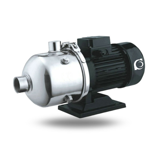
CHL Stainless Steel Horizontal Multistage Pump is a stainless steel wetted horizontal multistage centrifugal pump designed for clean water and mildly corrosive liquid boosting applications.
It provides stable high head and constant pressure output for systems requiring continuous and energy-efficient operation.
It is widely applied in water treatment systems, industrial liquid transfer lines, HVAC circulation systems, and pressure boosting installations.
Model Designation

Applications
- RO & high-rise: stable pressure boosting
- Industrial/food/chemical: corrosion-resistant transfer
- HVAC: chilled/hot water, stable temperature
- Building: constant-pressure water supply
Engineering Advantages
- Stainless steel wetted components ensure corrosion resistance and long-term hydraulic stability
- Horizontal multistage sectional design enables flexible head adjustment and high pressure efficiency
- Precision-machined impeller and diffuser alignment reduces hydraulic loss and improves efficiency
- Balanced rotor structure minimizes vibration and extends bearing service life
The pump adopts stainless steel flow path construction combined with multistage hydraulic energy transfer for stable continuous-duty boosting applications.
System Components
CHL Stainless Steel Horizontal Multistage Pump:
- Stainless steel pump casing
- Multistage impellers
- Diffusers
- Shaft and shaft sleeve
- Mechanical seal assembly
- Bearing housing and deep groove ball bearings
- Motor coupling
Technical Specifications
Service Conditions
- Suitable for clean water or mildly corrosive liquids without solid particles
- Indoor or protected outdoor installation
- Ambient temperature ≤ 40°C
Operating Conditions
- Flow rate: 2–20 m³/h
- Head: 8.5–50 m
- Power range: 0.37–4 kW
- Speed: 2900 rpm
- Liquid temperature: ≤ 120°C
- Working pressure: ≤ 1.6 MPa
Detailed parameter tables are provided below.
Installation & Dimensions
Outline Drawing

Performance Data
| No. | Name | Material | AISI/ASTM | No. | Name | Material | AISI/ASTM |
| 1 | Inlet/Outlet Section | Stainless Steel | AISI304 | 8 | Mechanical Seal |
|
|
| 2 | Connection Pipe | Stainless Steel | AISI304 | 9 | Motor End Cover | Aluminum Alloy | |
| 3 | Pressure Plate | Stainless Steel | AISI304 | 10 | Base | Cast Iron | ASTM258 |
| 4 | Impeller | Stainless Steel | AISI304 | 11 | Quick Coupling | Stainless Steel | AISI304 |
| 5 | Shaft | Stainless Steel | AISI304 | 12 | Diffuser | Stainless Steel | AISI304 |
| 6 | End Cover | Stainless Steel | AISI304 | 13 | Support Diffuser | Stainless Steel | AISI304 |
| 7 | Discharge Diffuser | Stainless Steel | AISI304 | 14 | Flow Guide | Stainless Steel | AISI304 |
Performance Parameters
| Model | Head (m) | Flow Rate (m³/h) | Power (kW) | Speed (rpm) |
| CHL2-20 | 14 | 2 | 0.37 | 2900 |
| CHL2-30 | 21 | 2 | 0.55 | 2900 |
| CHL2-40 | 28 | 2 | 0.55 | 2900 |
| CHL2-50 | 35 | 2 | 0.55 | 2900 |
| CHL2-60 | 42 | 2 | 0.75 | 2900 |
| CHL4-20 | 15 | 4 | 0.55 | 2900 |
| CHL4-30 | 22 | 4 | 0.75 | 2900 |
| CHL4-40 | 30 | 4 | 0.75 | 2900 |
| CHL8-10 | 8.5 | 8 | 0.75 | 2900 |
| CHL8-20 | 17 | 8 | 0.75 | 2900 |
| CHL8-30 | 25.5 | 8 | 1.1 | 2900 |
| CHL8-40 | 34 | 8 | 1.5 | 2900 |
| CHL8-50 | 42.5 | 8 | 2.2 | 2900 |
| Model | Head (m) | Flow Rate (m³/h) | Power (kW) | Speed (rpm) |
| CHL12-10 | 9.5 | 12 | 0.75 | 2900 |
| CHL12-20 | 19.5 | 12 | 1.2 | 2900 |
| CHL12-30 | 29.5 | 12 | 1.8 | 2900 |
| CHL12-40 | 39.5 | 12 | 2.4 | 2900 |
| CHL12-50 | 50 | 12 | 3 | 2900 |
| CHL16-10 | 10 | 16 | 1.1 | 2900 |
| CHL16-20 | 21 | 16 | 2.2 | 2900 |
| CHL16-30 | 32 | 16 | 3 | 2900 |
| CHL20-10 | 9.5 | 20 | 1.1 | 2900 |
| CHL20-20 | 21 | 20 | 2.2 | 2900 |
| CHL20-30 | 33 | 20 | 4 | 2900 |
How to Select a Pump Model
- Determine required flow rate and head; ensure duty point falls within high-efficiency range
- Confirm liquid characteristics including temperature and corrosion level
- Verify allowable working pressure of system pipeline
- Select motor power according to hydraulic load and service factor
- Consider installation layout and inlet/outlet orientation
Engineering Notes
- Not suitable for liquids containing abrasive solids
- Suction condition must avoid cavitation risk
- Pipeline support must prevent excessive nozzle load
- Ensure proper alignment between pump and motor
Compliance & Quality Assurance
- Factory hydraulic performance testing
- Hydrostatic pressure testing of pump casing
- Rotor dynamic balance inspection
- Material traceability documentation
Optional third-party inspection available
Safety Notice
- Do not operate under dry-running condition
- Ensure suction system is fully primed before startup
- Do not exceed rated working pressure
- Disconnect power before maintenance
OEM & Customization
This pump series supports engineered configuration and duty-based matching. Technical adjustments can be made according to system requirements and installation conditions.
Available options include:
- Motor voltage & frequency
- Mechanical seal type and configuration
- Wetted parts material selection
- Surface coating and corrosion protection
Configuration is determined based on duty point and project specifications.
FAQs
Q: Can the pump operate under VFD control?
A: Yes, operation under VFD is permitted within rated hydraulic limits.
Q: What is the allowable working pressure?
A: Maximum allowable working pressure is 1.6 MPa.
Q: What sealing options are available?
A: Mechanical seal configurations are standard.
Q: What type of liquid is permitted?
A: Clean water or mildly corrosive liquids without solid particles.
Q: What rotational speed is available?
A: Standard speed is 2900 rpm.
Q: Is the pump suitable for high-temperature applications?
A: Yes, liquid temperature up to 120°C is permitted within specification limits.