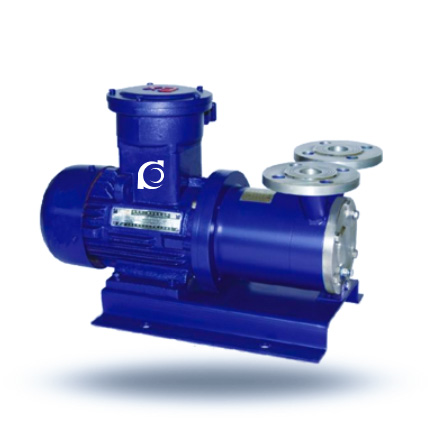
Product Overview
The CWB Magnetic Drive Vortex Chemical Pump is a seal-less magnetic-coupled vortex pump designed for leak-free transfer of corrosive and hazardous chemical liquids.
Traditional chemical pumps suffer from mechanical seal leakage, crystallization blockage, corrosion failure, and high maintenance risk in aggressive media applications.
Widely used in chemical processing, electroplating, pharmaceutical transfer, acid–alkali circulation, and hazardous liquid handling systems requiring strict environmental safety standards.
Model Designation

Applications
Typical Operating Scenarios
- Sealed transfer of corrosive chemical liquids in processing lines
- Hazardous media pumping in chemical and petrochemical plants
- Pharmaceutical reagent circulation with stringent safety requirements
- Environmental protection systems handling toxic or flammable effluents
- Small flow, high head applications with zero leakage necessity
Engineering Advantages
Structural Design Logic + Engineering Result
- Permanent magnetic coupling design eliminates mechanical seal dynamic leakage paths and achieves fully sealed torque transmission.
- Vortex/regenerative impeller structure generates stable hydraulic performance in low-flow, high-head applications without clogging.
- Self-lubricating sliding bearings and cooling circuit extend service life and reduce maintenance in continuous duty.
- Corrosion-resistant wetted components (plastics, ceramics, stainless steel) match aggressive chemical media.
System Components
CWB Magnetic Drive Vortex Chemical Pump mainly consists of:
- Permanent magnetic coupling assembly
- Cantilever vortex impeller
- Sliding bearings with circulation path
- Corrosion-resistant pump casing
- Containment shell
- Motor
Technical Specifications
Service Conditions
• Pump for sealed transfer of chemical media with susceptibility to leakage.
Operating Conditions
| Parameter | Value |
|---|---|
| Flow rate | 0.72 – 14.4 m³/h |
| Head | 20 – 120 m |
| Speed | 2900 rpm |
| Motor power | 1.1 – 15 kW |
| Liquid temperature | ≤ ~40°C |
| Working pressure | ≤ Typical magnetic pump design |
Detailed parameter tables are provided below.
Installation & Dimensions
Outline Drawing

Performance Data
| 1 | Pump Casing | 9 | Pump Shaft |
| 2 | Impeller | 10 | Inner Magnetic Rotor |
| 3 | Pump Cover | 11 | Inner Rotor Nut |
| 4 | Impeller Nut | 12 | Isolation Sleeve |
| 5 | Thrust Ring | 13 | Outer Magnet Assembly |
| 6 | Seal Ring | 14 | Support Frame |
| 7 | Sliding Bearing Sleeve | 15 | Motor |
| 8 | Shaft Sleeve |
Performance Parameters
| Model |
Flow Q
(m³/h) |
Head
(m) |
Speed n
(r/min) |
Efficiency η
(%) |
Motor Power
(kW) |
| CWB20-20 | 0.72 | 20 | 2900 | 22 | 1.1 |
| CWB20-40 | 0.72 | 40 | 2900 | 18 | 1.1 |
| CWB20-65 | 0.72 | 65 | 2900 | 15 | 2.2 |
| CWB25-25 | 1.44 | 25 | 2900 | 26 | 1.1 |
| CWB25-40 | 1.44 | 40 | 2900 | 24 | 1.5 |
| CWB25-75 | 1.44 | 75 | 2900 | 20 | 4 |
| CWB32-30 | 2.88 | 30 | 2900 | 28 | 2.2 |
| CWB32-50 | 2.88 | 50 | 2900 | 26 | 3 |
| CWB32-75 | 2.88 | 75 | 2900 | 22 | 5.5 |
| CWB32-120 | 2.88 | 120 | 2900 | 18 | 7.5 |
| CWB40-40 | 5.4 | 40 | 2900 | 30 | 5.5 |
| CWB40-90 | 5.4 | 90 | 2900 | 26 | 11 |
| CWB50-45 | 9 | 45 | 2900 | 30 | 7.5 |
| CWB65-50 | 14.4 | 50 | 2900 | 35 | 15 |
| Note: Wetted parts are available in 304, 304L, 316 and 316L. Non-standard magnetic vortex pumps can be customized according to customer requirements. | |||||
How to Select a Pump Model
- Determine required flow and head according to process design.
- Verify medium characteristics (corrosiveness, volatility, toxicity).
- Match wetted material selection with fluid compatibility.
- Confirm allowable operating temperature and viscosity constraints.
- Specify optional features (cooling circuit, bearing options) for continuous duty.
Engineering Notes
- Magnetic drive eliminates dynamic sealing points, reducing leakage and maintenance.
- Vortex impeller design suits low flow with solid-tolerant performance.
- Cooling circuit ensures thermal equilibrium of magnetic coupling.
- Sliding bearings rely on medium for lubrication; avoid dry running.
Compliance & Quality Assurance
- Factory hydraulic performance testing with flow/head curves.
- Containment shell pressure integrity and magnetic coupling torque verification.
- Material traceability for wetted components.
- Optional third-party inspection available.
Safety Notice
- Do not operate under dry-running conditions.
- Ensure correct priming before startup.
- Disconnect power before any service.
- Avoid exceeding rated temperature or pressure.
OEM & Custom
This pump series supports engineered configuration and duty-based matching. Technical adjustments can be made according to system requirements and installation conditions.
Available options include:
• Wetted materials (304/316/316L / plastics / ceramics)
• Magnetic coupling torque rating
• Motor voltage & frequency
• Cooling circuit configuration
Configuration is determined based on duty point and project specifications.
FAQs
Q1: Can this pump handle flammable liquids?
A1: Yes, designed for corrosive, flammable, explosive, and toxic liquids.
Q2: What is the maximum allowable viscosity?
A2: Recommended kinematic viscosity ≤ 5×10⁻⁶ m²/s.
Q3: What materials are available for wetted parts?
A3: Stainless steel (304/316/316L), engineering plastics, and ceramics.
Q4: Can it operate under variable frequency drive (VFD)?
A4: Yes, within rated speed and torque limits.
Q5: What is the allowable working pressure?
A5: Typically within the magnetic pump design limit (≤ nominal design).
Q6: Does the pump include a cooling system?
A6: Yes, internal circulation cooling circuit for magnetic-bearing thermal control.
Q7: Are customization options available?
A7: Yes, OEM & Custom configurations are supported.