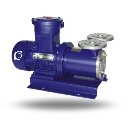
Product Overview
CWB Vortex Magnetic Pump is a horizontal seal-less magnetic-drive vortex centrifugal pump designed for high-head transfer of corrosive chemical liquids.
It eliminates mechanical shaft seal failure risk under high-pressure corrosive service, preventing hazardous media leakage and environmental contamination.
It is applied in chemical processing, pharmaceutical production and petrochemical systems requiring sealed high-head transfer of toxic or flammable liquids.
Model Designation

Application Scenarios
Typical Operating Scenarios
- High-head transfer of corrosive acids and alkalis
- Leak-sensitive hazardous chemical conveyance
- Petrochemical fluid circulation under sealed conditions
- Pharmaceutical and fine chemical processing lines
- Corrosion-resistant transfer systems for volatile toxic liquids
(CWB vortex magnetic pumps are designed with sealed magnetic drive and corrosion-resistant materials for demanding chemical service.)
Engineering Advantages
Structural Logic + Engineering Result
CWB magnetic vortex pumps replace dynamic shaft seals with permanent-magnet coupling and static sealing housing, creating a fully enclosed wetted flow path that eliminates mechanical seal leakage. High-strength corrosion-resistant materials and a compact vortex design provide stable high-head performance and reduced clogging risk. Self-lubricating circulation paths extend bearing life and improve operational reliability.
System Components
CWB Vortex Magnetic Pump mainly consists of:
- Pump casing
- Vortex impeller
- Permanent magnet coupling (inner & outer rotors)
- Static sealing housing
- Sliding bearing sleeves
- Shaft sleeve
- Motor
Technical Data
Service Conditions
- Corrosive chemical liquids compatible with wetted materials
- Medium viscosity: ≤ 5×10⁻⁶ m²/s
- Horizontal installation in sealed systems
Operating Conditions
| Parameter | Value / 范围 |
|---|---|
| Flow rate | 0.72 – 14.4 m³/h |
| Head | 20 – 120 m |
| Power range | 1.1 – 15 kW (approx.) |
| Speed | 2900 rpm |
| Liquid temperature | ≤ (depends on materials) |
| Working pressure | ≤ typically ≤ nominal pump design |
Detailed parameter tables are provided below.
Specifications & Installation
Outline Drawing

Performance Data
| 1 | Pump casing | 9 | Pump shaft |
| 2 | Impeller | 10 | Inner magnetic rotor |
| 3 | Pump cover | 11 | Inner rotor nut |
| 4 | Impeller nut | 12 | Containment shell |
| 5 | Thrust ring | 13 | Outer magnet assembly |
| 6 | Sealing ring | 14 | Mounting bracket |
| 7 | Sliding bearing sleeve | 15 | Motor |
| 8 | Shaft sleeve |
Performance Parameters
| Model |
Flow Q
(m³/h) |
Head
(m) |
Speed n
(r/min) |
Efficiency η
(%) |
Motor power
(kW) |
| CWB20-20 | 0.72 | 20 | 2900 | 22 | 1.1 |
| CWB20-40 | 0.72 | 40 | 2900 | 18 | 1.1 |
| CWB20-65 | 0.72 | 65 | 2900 | 15 | 2.2 |
| CWB25-25 | 1.44 | 25 | 2900 | 26 | 1.1 |
| CWB25-40 | 1.44 | 40 | 2900 | 24 | 1.5 |
| CWB25-75 | 1.44 | 75 | 2900 | 20 | 4 |
| CWB32-30 | 2.88 | 30 | 2900 | 28 | 2.2 |
| CWB32-50 | 2.88 | 50 | 2900 | 26 | 3 |
| CWB32-75 | 2.88 | 75 | 2900 | 22 | 5.5 |
| CWB32-120 | 2.88 | 120 | 2900 | 18 | 7.5 |
| CWB40-40 | 5.4 | 40 | 2900 | 30 | 5.5 |
| CWB40-90 | 5.4 | 90 | 2900 | 26 | 11 |
| CWB50-45 | 9 | 45 | 2900 | 30 | 7.5 |
| CWB65-50 | 14.4 | 50 | 2900 | 35 | 15 |
| Note: Wetted parts are available in 304, 304L, 316 and 316L; non-standard magnetic vortex pumps can be customized according to customer requirements. | |||||
How to Select a Pump Model
- Confirm required high-head and flow duty point.
- Verify corrosive medium compatibility with wetted material options (e.g., SS, ceramics, plastics).
- Check viscosity requirement (≤5×10⁻⁶ m²/s) to ensure efficiency.
- Match pump model curve with system head & NPSH conditions.
- Confirm horizontal orientation installation parameters.
Engineering Notes
- Vortex impeller structure provides high head at low flow but has lower efficiency relative to standard centrifugal pumps.
- Magnetic drive eliminates mechanical seals, reducing leakage and maintenance.
- Self-lubricating sliding bearings rely on medium circulation for lubrication.
- Not suitable for highly viscous (>specified) or abrasive slurries.
Compliance & Quality Assurance
- Factory hydraulic performance verification and curve testing.
- Material traceability for wetted corrosion-resistant components.
- Isolation housing leakage integrity test.
- Dynamic balance test for magnetic rotors.
- Optional third-party inspection upon request.
Safety Notices
- Do not operate under dry-running conditions.
- Ensure proper priming and system fill before startup.
- Avoid exceeding rated temperature and pressure.
- Disconnect electrical supply before servicing.
OEM & Customization
This pump series supports engineered configuration and duty-based matching. Technical adjustments can be made according to system requirements and installation conditions.
Available options include:
• Corrosion-resistant wetted material selection (304, 316, ceramics, plastics)
• Motor voltage & frequency
• Cooling circuit optimization for viscous media
• Customized performance curve matching
Configuration is determined based on duty point and project specifications.
FAQs
Q: Can the pump operate under VFD control?
A: Yes, within rated speed and load conditions.
Q: What is the allowable working pressure?
A: Usually aligned with model design; consult detailed curves.
Q: What seal strategy does the CWB pump use?
A: Seal-less magnetic drive with static isolation housing.
Q: What materials are available for wetted parts?
A: 304, 304L, 316, 316L stainless steel and high-strength plastics.
Q: Is it suitable for viscous media?
A: Suitable for viscosity ≤5×10⁻⁶ m²/s; efficiency drops with higher viscosity.
Q: Can it handle flammable or toxic liquids?
A: Yes, the sealed magnetic drive is designed for corrosive, flammable, and toxic media.
Q: What standards does the pump comply with?
A: Meets industrial magnetic drive and centrifugal pump design standards with ISO9001/CE options.