Product Overview
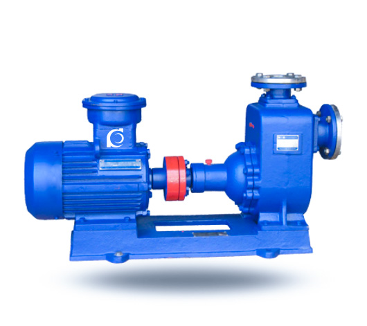
CYZ-A Horizontal Self-Priming Oil Pump is a single-stage, horizontal, self-priming centrifugal pump designed for transferring gasoline, diesel, kerosene, and other light oils.
It solves the issue of air removal in the suction line, ensuring stable and continuous operation even during frequent starts and stops.
Ideal for use in oil storage facilities, marine cargo systems, and tank truck operations where self-priming and high efficiency are required.
Model Designation

Applications
• Petroleum storage and transfer systems
• Marine cargo oil systems
• Tank truck loading and unloading operations
• Firefighting and ballast water systems
• Cooling water circulation systems in industrial processes
Engineering Advantages
• Self-priming capability: No foot valve required, simplifying system layout and reducing installation complexity.
• Reliable performance: Quick self-priming ensures uninterrupted operation even in fluctuating suction conditions.
• High-temperature adaptability: Capable of transferring fluids with temperatures up to 80°C, including seawater and freshwater.
• Durable construction: Built with corrosion-resistant materials, ensuring long-term, stable operation in harsh environments.
System Components
The CYZ-A Horizontal Self-Priming Oil Pump consists of the following main components:
• Pump casing (integrating suction chamber, liquid storage chamber, and separation box)
• Self-priming mechanism (air-liquid mixing and separation)
• Corrosion-resistant mechanical seals
• Cooling chamber (optional for higher temperature applications)
• Pump shaft and bearing components
Technical Parameters
Service Conditions
• Applicable Fluids: Gasoline, kerosene, diesel, aviation fuel, seawater, or freshwater
• Operating Temperature: ≤ 80°C
Operating Conditions
- Flow Rate: 3.2 – 500 m³/h
- Head: 12 – 80 m
- Power Range: 0.75 – 110 kW
- Speed: 1450 / 2900 rpm
- Liquid Temperature: ≤ 80°C
- Working Pressure: ≤ 1.0 MPa
Detailed parameter tables are provided below.
Specifications & Installation
Outline Drawing

Performance Data
| 1 | Coupling | 2 | Pump Shaft | 3 | Bearing | 4 | Mechanical Seal | 5 | Bearing Housing | 6 | Pump Shell | 7 | Discharge Seat |
| 8 | Suction Seat | 9 | Front Sealing Ring | 10 | Impeller | 11 | Rear Cover | 12 | Water Ring | 13 | Liquid Injection Hole | 14 | Return Liquid Hole |
Performance Parameters
| Model |
Flow Rate (m³/h)
|
Head (m)
|
Efficiency (%)
|
Speed (rpm)
|
Motor Power (kW)
|
Diameter
|
||
| (m3/h) |
(l/s)
|
(m) | (%) | (r/min) | (KW) |
suction
|
discharge
|
|
| 25CYZ-A-20 | 3.2 | 0.9 | 20 | 6.5 | 2900 | 0.75 | 25 | 25 |
| 25CYZ-A-32 | 3.2 | 0.9 | 32 | 6.5 | 2900 | 1.1 | 25 | 25 |
| 40CYZ-A-20 | 6.3 | 1.8 | 20 | 6.5 | 2900 | 1.1 | 40 | 32 |
| 40CYZ-A-40 | 10 | 2.8 | 40 | 6.5 | 2900 | 4 | 50 | 40 |
| 50CYZ-A-12 | 15 | 4.2 | 12 | 6.5 | 2900 | 1.6 | 50 | 50 |
| 50CYZ-A-20 | 18 | 5 | 20 | 6.5 | 2900 | 2.2 | 50 | 50 |
| 50CYZ-A-30 | 20 | 5.5 | 30 | 6.5 | 2900 | 4 | 50 | 50 |
| 50CYZ-A-40 | 10 | 2.8 | 40 | 6.5 | 2900 | 4 | 50 | 50 |
| 50CYZ-A-50 | 12.5 | 3.5 | 50 | 6.5 | 2900 | 5.5 | 50 | 50 |
| 50CYZ-A-60 | 15 | 4.2 | 60 | 6.5 | 2900 | 7.5 | 50 | 50 |
| 50CYZ-A-75 | 20 | 5.6 | 75 | 6.5 | 2900 | 11 | 50 | 50 |
| 65CYZ-A-15 | 30 | 8.3 | 15 | 6.5 | 2900 | 3 | 65 | 50 |
| 65CYZ-A-32 | 25 | 6.9 | 32 | 6.5 | 2900 | 5.5 | 65 | 50 |
| 80CYZ-A-13 | 35 | 9.7 | 13 | 6 | 2900 | 3 | 80 | 65 |
| 80CYZ-A-17 | 43 | 12 | 17 | 6 | 2900 | 4 | 80 | 65 |
| 80CYZ-A-22 | 40 | 11.1 | 22 | 6 | 2900 | 5.5 | 80 | 65 |
| 80CYZ-A-25 | 50 | 13.9 | 25 | 6 | 2900 | 7.5 | 80 | 80 |
| 80CYZ-A-32 | 50 | 13.9 | 32 | 6 | 2900 | 7.5 | 80 | 80 |
| 80CYZ-A-55 | 60 | 16.7 | 55 | 6 | 2900 | 18.5 | 80 | 80 |
| 80CYZ-A-70 | 60 | 16.7 | 70 | 6 | 2900 | 22 | 80 | 80 |
| 100CYZ-A-20 | 100 | 27.8 | 20 | 6 | 2900 | 11 | 100 | 80 |
| 100CYZ-A-40 | 100 | 27.8 | 40 | 6 | 2900 | 22 | 100 | 100 |
| 100CYZ-A-40A | 100 | 27.8 | 40 | 6 | 2900 | 22 | 100 | 100 |
| 10065CYZ-A-65 | 100 | 27.8 | 65 | 6 | 2900 | 30 | 100 | 100 |
| 100CYZ-A-75 | 70 | 19.4 | 75 | 6 | 2900 | 30 | 100 | 100 |
| 150CYZ-A-45 | 170 | 47.2 | 45 | 5 | 2900 | 37 | 150 | 100 |
| 150CYZ-A-55 | 170 | 47.2 | 55 | 5 | 2900 | 45 | 150 | 100 |
| 150CYZ-A-65 | 170 | 47.2 | 65 | 5 | 2900 | 55 | 150 | 100 |
| 150CYZ-A-80 | 160 | 44.4 | 80 | 5 | 2900 | 55 | 150 | 100 |
| 200CYZ-A-63 | 280 | 77.8 | 63 | 5 | 1450 | 90 | 200 | 150 |
| 250CYZ-A-50 | 400 | 111.1 | 50 | 5 | 1450 | 90 | 250 | 200 |
| 300CYZ-A-50 | 500 | 138.9 | 50 | 5 | 1450 | 110 | 300 | 250 |
Performance Curves

Outline Drawing(2)

Performance Data(2)
| 1 | Pump | |
| 2 | Pressure Gauge | |
| 3 | Discharge Vertical Pipe | |
| 4 | Suction Hard Pipe | |
| 5 | Elbow | |
| 6 | Flow Control Valve | |
| 7 | Discharge Pipeline | |
| 8 | Liquid Filling Plug | |
| 9 | Vacuum Gauge | |
PrecautionsInstallation &Requirements
|
||
Pump Pressure Control Range Chart
| Pump Model and Fluid Type | water | gasoline-powered pump | kerosene | diesel |
| 25CYZ-A-20 | 0.13-0.23 | 0.09-0.15 | 0.10-0.18 | 0.10-0.19 |
| 25CYZ-A-32 | 0.28-0.38 | 0.20-O.27 | 0.21-0.29 | 0.23-0.32 |
| 40CYZ-A-20 | 0.15-0.25 | 0.11-O.18 | 0.12-0.20 | 0.12-0.2l |
| 40CYZ-A-40 | 0.33-O.41 | 0.24-0.30 | 0.26-0.33 | 0.28-0.35 |
| 50CYZ-A-12 | 0.10-0.15 | 0.07-0.11 | 0.08-O.12 | 0.08-0.13 |
| 50CYZ-A-20 | 0.15-O.25 | 0.11-0.18 | 0.12-0.20 | 0.12-0.21 |
| 50CYZ-A-30 | 0.29-0.39 | 0.21-0.28 | 0.22-O.30 | 0.24-0.33 |
| 50CYZ-A-35 | 0.30-0.40 | 0.22-0.29 | 0.23-0.31 | 0.25-0.33 |
| 50CYZ-A-40 | 0.33-0.41 | 0.24-0.30 | 0.26-O.33 | 0.28-O.35 |
| 50CYZ-A-50 | 0.45-0.64 | O.33-0.47 | 0.36-0.46 | 0.38-0.49 |
| 50CYZ-A-60 | 0.55-0.65 | 0.40-0.47 | 0.48-0.60 | 0.47-0.55 |
| 50CYZ-A-75 | 0.72-0.78 | 0.53-O.57 | 0.58-0.62 | 0.61-0.66 |
| 65CYZ-A-15 | 0.12-0.20 | 0.09-O.13 | 0.09-0.14 | 0.10-0.15 |
| 65CYZ-A-32 | 0.29-0.39 | 0.21-0.28 | 0.22-O.30 | 0.24-0.33 |
| 80CYZ-A-13 | 0.10-0.15 | 0.07-0.11 | 0.08-0.12 | 0.08-0.13 |
| 80CYZ-A-17 | 0.13-0.21 | 0.09-0.15 | 0.10-O.17 | 0.11-O.18 |
| 80CYZ-A-22 | 0.19-0.26 | 0.13-0.20 | 0.14-0.21 | 0.14-0.22 |
| 80CYZ-A-25 | 0.21-0.28 | O.15-0.20 | 0.17-0.22 | 0.18-0.24 |
| 80CYZ-A-32 | 0.28-0.36 | 0.20-O.26 | 0.22-0.29 | 0.24-0.31 |
| 80CYZ-A-55 | 0.54-0.62 | 0.39-O.45 | 0.43-0.50 | 0.46-0.53 |
| 80CYZ-A-70 | 0.66-0.76 | 0.48-0.55 | 0.53-0.61 | 0.56-0.65 |
| 100CYZ-A-20 | 0.18-0.28 | 0.14-0.22 | 0.15-O.23 | O.15-0.24 |
| 100CYZ-A-40 | 0.37-0.49 | 0.27-0.36 | 0.30-O.39 | 0.31-0.39 |
| 100CYZ-A-40A | 0.35-0.46 | 0.26-0.34 | 0.28-0.37 | 0.30-O.39 |
| 100CYZ-A-65 | 0.60-0.68 | 0.44-0.50 | 0.48-0.54 | 0.51-0.58 |
| 100CYZ-A-75 | 0.72-0.78 | 0.53-0.57 | 0.58-O.63 | 0.61-0.66 |
| 150CYZ-A-55 | 0.52-0.58 | 0.38-0.42 | 0.42-0.46 | 0.44-0.49 |
| 150CYZ-A-65 | 0.60-0.66 | 0.44-0.48 | 0.48-0.53 | 0.51-0.56 |
| 150CYZ-A-80 | 0.72-0.77 | 0.53-0.56 | 0.56-O.62 | 0.61-0.65 |
| 200CYZ-A-63 | 0.63-0.69 | 0.45-O.5l | 0.51-O.53 | 0.53-0.58 |
| 250CYZ-A-50 | 0.45-0.60 | 0.33-0.44 | 0.36-0.46 | 0.38-O.49 |
How to Select a Pump Model
• Identify required flow rate for your system based on the oil transfer volume.
• Choose the appropriate pump head depending on your system’s pressure requirements.
• Ensure compatibility with the fluid type being transferred (e.g., gasoline, kerosene, or diesel).
• Consider the operating temperature to select a model with the appropriate seals and materials.
Engineering Notes
• Pre-fill the pump casing with liquid before startup to ensure quick self-priming.
• Monitor for air pockets in the suction line to avoid inefficient pumping and cavitation.
• Check seals and bearings regularly for wear and replace them as needed to maintain performance.
• Use proper filtration to avoid clogging the pump and reducing flow efficiency.
Compliance & Quality Assurance
• Factory testing to ensure proper operation under designed flow and pressure conditions.
• Hydraulic performance testing to validate system efficiency and stability.
• Material traceability for all wetted parts to ensure high-quality construction.
• Third-party inspections available for additional validation and assurance.
Safety Notice
• Ensure proper priming before starting the pump to avoid dry running.
• Monitor suction pressure to prevent cavitation and pump damage.
• Disconnect power before performing any maintenance or adjustments.
• Regularly inspect seals for wear and tear to maintain efficiency and prevent leaks.
OEM & Custom
This pump series supports engineered configuration and duty-based matching.
Available options include:
• Motor voltage & frequency
• Mechanical seal type and configuration
• Wetted parts material selection
• Surface coating and corrosion protection
FAQs
Q: What is the maximum allowable fluid temperature?
A: The pump can handle fluids up to 80°C.
Q: Can the pump operate in environments with fluctuating suction conditions?
A: Yes, the pump is designed for reliable operation even with varying suction conditions.
Q: What type of seals are used in the pump?
A: The pump uses corrosion-resistant mechanical seals suitable for various fluids.
Q: What is the recommended maintenance schedule for the pump?
A: It is recommended to inspect the seals and bearings every 6 months and replace as needed.
Q: Can the pump handle seawater?
A: Yes, the pump can handle seawater, making it ideal for marine applications.