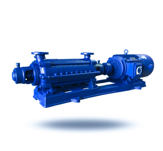
D/DG Horizontal Multistage Centrifugal Pump High Pressure
D/DG Horizontal Multistage Centrifugal Pump | Segmental multistage high-head package for clean-water and boiler-feed duty
- Segmental multistage build: Stage-configured pressure rise for high-head system requirements.
- High-efficiency hydraulics: Wide operating range with stable, predictable performance.
- Smooth continuous duty: Low-noise running with controlled vibration for long service life.
- Seal & material options: Packing or mechanical seal; configurable for hot water, oils, and mild corrosion.