Product Overview
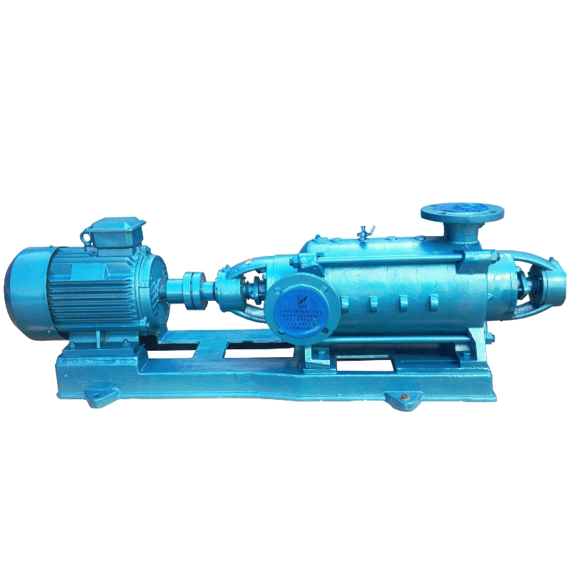
The D Series Single-Suction Multistage Clean Water Centrifugal Pump is a horizontal segmented multistage pump designed for continuous water supply applications. By connecting multiple impellers in series, it delivers high head output and is suitable for industrial and municipal systems requiring stable operation, high reliability, and easy maintenance.
This pump is suitable for conveying clean water or other liquids with physical and chemical properties similar to water. By replacing wetted parts, adjusting the sealing structure, and adding a cooling system, it can also be adapted for hot water, light corrosive liquids, oils, or media containing fine particles.
Model Designation

Key Features
-
Multistage sectional design with compact structure; head can be flexibly adjusted by changing the number of stages to suit various operating conditions.
-
High-quality cast iron impellers and casings ensure strong structural integrity and long service life with stable operation.
-
High assembly precision and optimized flow path design result in high efficiency and low energy consumption.
-
All wetted and sealing components are replaceable, facilitating maintenance and inspection.
Engineering Summary
The D Series horizontal single-suction multistage pump features high efficiency, wide performance range, low noise, stable operation, long service life, and ease of installation and maintenance. It complies with JB/T 1051-93 “Multistage Clean Water Centrifugal Pumps – Types and Basic Parameters.”
The series is designed using Computer-Aided Engineering (CAE) and manufactured with mature processes and a complete quality control system to ensure performance consistency and product reliability.
It is widely used in water supply and drainage systems, high-rise building pressure boosting, landscape irrigation, firefighting systems, long-distance water transfer, heating circulation, domestic hot water supply, and auxiliary equipment systems. Especially suitable for small boiler feedwater applications.
Typical Applications
-
Industrial and municipal water supply and drainage systems
-
Pressure boosting systems in high-rise buildings
-
Landscaping and agricultural irrigation
-
Fire protection booster and stabilizing systems
-
Long-distance water transport and heating systems
-
Domestic hot water circulation and boiler feed systems
-
Auxiliary systems in industrial equipment water networks
System & Operation
Components & Supply
-
Horizontal inlet and vertical upward discharge nozzle layout, allowing convenient piping connection.
-
Main casing components are cast iron with high strength and pressure resistance.
-
Impellers are made of precision-cast iron with internal guide vanes for improved energy conversion.
-
Shaft is made of high-quality carbon steel and assembled with sleeves, locking nuts, and coupling for direct motor connection.
Technical Specifications
Operating Conditions
-
Suitable for clean water or liquids with physical and chemical properties similar to water; minimal suspended particles allowed.
-
Maximum medium temperature up to 110°C; sealing system can be adapted based on fluid properties.
-
Pump rotates clockwise when viewed from the drive end; operating pressure is stage-dependent and must stay within design limits.
-
Recommended for use in closed systems to maintain stable suction and prevent cavitation.
Service Conditions
-
Indoor installation is recommended; avoid exposure to high humidity or corrosive gases.
-
Ambient temperature ≤ 40°C; relative humidity ≤ 95%.
-
Installation base must be level and vibration-free; anti-vibration measures should be taken if required.
-
For outdoor use, protective covers and sealing measures are necessary to prevent ingress of rainwater or debris.
Protection Functions
-
Motor should be equipped with thermal overload and phase-failure protection.
-
Check valves and pressure relief valves should be installed at the outlet to prevent backflow and water hammer.
-
Critical systems should include monitoring and alarm functions for pressure, temperature, and flow rate.
-
The pump must not run dry or start without liquid; use liquid level interlocks when necessary.
Selection Criteria
-
Determine pump model and number of stages based on required head and flow to ensure efficient operation point.
-
Select materials and sealing type according to fluid temperature, corrosiveness, and viscosity.
-
Installation layout defines nozzle orientation, motor power, and overall pump dimensions.
-
For continuous-duty systems, install standby pump(s) or alternate operation modes to enhance reliability.
-
Consider maintenance cycles and parts standardization to reduce long-term operation and service costs.
Installation & Dimensions
Outline Drawing

Performance Data
| 1 | Bearing Cover | 2 | Nut | 3 | Bearing | 4 | Water Baffle Sleeve | 5 | Bearing Bracket | 6 | Front Shaft Sleeve | 7 | Packing Gland | 8 | Packing Ring |
| 9 | Suction Section | 10 | Intermediate Sleeve | 11 | Seal Ring | 12 | Impeller | 13 | Middle Section | 14 | Diffuser Baffle | 15 | Diffuser Sleeve | 16 | Tightening Bolt |
| 17 | Discharge Diffuser | 18 | Balance Ring | 19 | Balance Ring | 20 | Balance Plate | 21 | Discharge Section | 22 | Tail Cover | 23 | Shaft | 24 | Rear Shaft Sleeve |
Performance Parameters
| Model | Stages | Flow (Q) | Head (m) | Speed (r/min) | Power (kW) | NPSHr (m) | Efficiency η (%) | ||
| m³/h | L/s | Shaft Power | Motor Power | ||||||
| 50D8×2 | 2 | 18 | 5 | 19 | 2950 | 1.5 | 2.2 | 2.3 | 62 |
| 50D8×3 | 3 | 18 | 5 | 28.5 | 2950 | 2.25 | 3 | 2.3 | 62 |
| 50D8×4 | 4 | 18 | 5 | 38 | 2950 | 3 | 4 | 2.3 | 62 |
| 50D8×5 | 5 | 18 | 5 | 47.5 | 2950 | 3.75 | 5.5 | 2.3 | 62 |
| 50D8×6 | 6 | 18 | 5 | 57 | 2950 | 4.5 | 5.5 | 2.3 | 62 |
| 50D8×7 | 7 | 18 | 5 | 66.5 | 2950 | 5.25 | 7.5 | 2.3 | 62 |
| 50D8×8 | 8 | 18 | 5 | 76 | 2950 | 6 | 7.5 | 2.3 | 62 |
| 50D8×9 | 9 | 18 | 5 | 85.5 | 2950 | 6.75 | 7.5 | 2.3 | 62 |
| 50D8×10 | 10 | 18 | 5 | 95 | 2950 | 7.5 | 11 | 2.3 | 62 |
| 50D8×11 | 11 | 18 | 5 | 104.5 | 2950 | 8.25 | 11 | 2.3 | 62 |
| 50D8×12 | 12 | 18 | 5 | 114 | 2950 | 9 | 11 | 2.3 | 62 |
| Model | Stages | Flow (Q) | Head (m) | Speed (r/min) | Power (kW) | NPSHr (m) | Efficiency η (%) | ||
| m³/h | L/s | Shaft Power | Motor Power | ||||||
| 80D12×2 | 2 | 32.4 | 9 | 22.7 | 2950 | 2.68 | 3 | 2.8 | 75 |
| 80D12×3 | 3 | 32.4 | 9 | 34.05 | 2950 | 4.02 | 5.5 | 2.8 | 75 |
| 80D12×4 | 4 | 32.4 | 9 | 45.4 | 2950 | 5.36 | 7.5 | 2.8 | 75 |
| 80D12×5 | 5 | 32.4 | 9 | 56.75 | 2950 | 6.7 | 7.5 | 2.8 | 75 |
| 80D12×6 | 6 | 32.4 | 9 | 68.1 | 2950 | 8.04 | 11 | 2.8 | 75 |
| 80D12×7 | 7 | 32.4 | 9 | 79.45 | 2950 | 9.38 | 11 | 2.8 | 75 |
| 80D12×8 | 8 | 32.4 | 9 | 90.8 | 2950 | 10.72 | 15 | 2.8 | 75 |
| 80D12×9 | 9 | 32.4 | 9 | 102.15 | 2950 | 11.06 | 15 | 2.8 | 75 |
| 80D12×10 | 10 | 32.4 | 9 | 113.5 | 2950 | 13.4 | 15 | 2.8 | 75 |
| 80D12×11 | 11 | 32.4 | 9 | 124.85 | 2950 | 14.74 | 18.5 | 2.8 | 75 |
| 80D12×12 | 12 | 32.4 | 9 | 136.2 | 2950 | 16.08 | 18.5 | 2.8 | 75 |
| Model | Stages | Flow (Q) | Head (m) | Speed (r/min) | Power (kW) | NPSHr (m) | Efficiency η (%) | ||
| m³/h | L/s | Shaft Power | Motor Power | ||||||
| 100D16×2 | 2 | 54 | 15 | 35.2 | 2950 | 7.2 | 11 | 3.3 | 71.5 |
| 100D16×3 | 3 | 54 | 15 | 52.8 | 2950 | 10.8 | 15 | 3.3 | 71.5 |
| 100D16×4 | 4 | 54 | 15 | 70.4 | 2950 | 14.4 | 18.5 | 3.3 | 71.5 |
| 100D16×5 | 5 | 54 | 15 | 88 | 2950 | 18 | 22 | 3.3 | 71.5 |
| 100D16×6 | 6 | 54 | 15 | 105.6 | 2950 | 21.6 | 30 | 3.3 | 71.5 |
| 100D16×7 | 7 | 54 | 15 | 123.2 | 2950 | 25.2 | 30 | 3.3 | 71.5 |
| 100D16×8 | 8 | 54 | 15 | 140.8 | 2950 | 28.8 | 37 | 3.3 | 71.5 |
| 100D16×9 | 9 | 54 | 15 | 158.4 | 2950 | 32.4 | 37 | 3.3 | 71.5 |
| 100D16×10 | 10 | 54 | 15 | 176 | 2950 | 36 | 45 | 3.3 | 71.5 |
| 100D16×11 | 11 | 54 | 15 | 198.6 | 2950 | 39.6 | 55 | 3.3 | 71.5 |
| 100D16×12 | 12 | 54 | 15 | 211.2 | 2950 | 43.2 | 55 | 3.3 | 71.5 |
| Model | Stages | Flow (Q) | Head (m) | Speed (r/min) | Power (kW) | NPSHr (m) | Efficiency η (%) | ||
| m³/h | L/s | Shaft Power | Motor Power | ||||||
| 125D25×2 | 2 | 108 | 30 | 40 | 2950 | 15.6 | 18.5 | 4 | 76 |
| 125D25×3 | 3 | 108 | 30 | 60 | 2950 | 23.4 | 30 | 4 | 76 |
| 125D25×4 | 4 | 108 | 30 | 80 | 2950 | 31.2 | 37 | 4 | 76 |
| 125D25×5 | 5 | 108 | 30 | 100 | 2950 | 39 | 45 | 4 | 76 |
| 125D25×6 | 6 | 108 | 30 | 120 | 2950 | 46.8 | 55 | 4 | 76 |
| 125D25×7 | 7 | 108 | 30 | 140 | 2950 | 54.6 | 75 | 4 | 76 |
| 125D25×8 | 8 | 108 | 30 | 160 | 2950 | 62.4 | 75 | 4 | 76 |
| 125D25×9 | 9 | 108 | 30 | 180 | 2950 | 70.3 | 90 | 4 | 76 |
| 125D25×10 | 10 | 108 | 30 | 200 | 2950 | 78 | 90 | 4 | 76 |
| Model | Stages | Flow (Q) | Head (m) | Speed (r/min) | Power (kW) | NPSHr (m) | Efficiency η (%) | ||
| m³/h | L/s | Shaft Power | Motor Power | ||||||
| 150D30×2 | 2 | 162 | 45 | 54.6 | 2950 | 31.46 | 37 | 4.1 | 76.6 |
| 150D30×3 | 3 | 162 | 45 | 81.9 | 2950 | 47.19 | 55 | 4.1 | 76.6 |
| 150D30×4 | 4 | 162 | 45 | 109.2 | 2950 | 62.92 | 75 | 4.1 | 76.6 |
| 150D30×5 | 5 | 162 | 45 | 136.5 | 2950 | 78.65 | 90 | 4.1 | 76.6 |
| 150D30×6 | 6 | 162 | 45 | 163.8 | 2950 | 94.38 | 110 | 4.1 | 76.6 |
| 150D30×7 | 7 | 162 | 45 | 191.1 | 2950 | 110.11 | 132 | 4.1 | 76.6 |
| 150D30×8 | 8 | 162 | 45 | 218.4 | 2950 | 125.84 | 160 | 4.1 | 76.6 |
| 150D30×9 | 9 | 162 | 45 | 245.7 | 2950 | 141.57 | 160 | 4.1 | 76.6 |
Installation Diagram

Performance Data(2)
| Model | Stages | L | L1 | L2 | L3 | L4 | L5 | B | B1 | H | H1 | H2 | H3 | H4 | n-φd |
| 50D8×2 | 2 | 960 | 65 | 490 | 730 | 135 | 345 | 355 | 290 | 230 | 160 | 90 | 100 | 25 | 4-φ20 |
| 50D8×3 | 3 | 1163 | 113 | 550 | 815 | 145 | 390 | 360 | 300 | 240 | 160 | 100 | 145 | 25 | 4-φ20 |
| 50D8×4 | 4 | 1141 | 136 | 580 | 890 | 180 | 410 | 360 | 340 | 242 | 160 | 112 | 153 | 25 | 4-φ20 |
| 50D8×5 | 5 | 1274 | 226 | 710 | 1120 | 270 | 485 | 370 | 370 | 242 | 160 | 132 | 183 | 25 | 4-φ20 |
| 50D8×6 | 6 | 1332 | 226 | 710 | 1120 | 270 | 485 | 370 | 370 | 242 | 160 | 132 | 183 | 25 | 4-φ20 |
| 50D8×7 | 7 | 1390 | 226 | 710 | 1120 | 270 | 485 | 370 | 370 | 242 | 160 | 132 | 183 | 25 | 4-φ20 |
| 50D8×8 | 8 | 1448 | 310 | 770 | 1230 | 300 | 485 | 370 | 370 | 242 | 160 | 132 | 183 | 25 | 4-φ20 |
| 50D8×9 | 9 | 1508 | 310 | 770 | 1230 | 300 | 485 | 370 | 370 | 242 | 160 | 132 | 183 | 25 | 4-φ20 |
| 50D8×10 | 10 | 1689 | 362 | 949 | 1515 | 420 | 610 | 370 | 405 | 255 | 160 | 160 | 225 | 25 | 4-φ20 |
| 50D8×11 | 11 | 1747 | 362 | 940 | 1515 | 420 | 610 | 370 | 405 | 255 | 160 | 160 | 225 | 25 | 4-φ20 |
| 50D8×12 | 12 | 1805 | 362 | 940 | 1515 | 420 | 610 | 370 | 405 | 255 | 160 | 160 | 225 | 25 | 4-φ20 |
| Model | Stages | L | L1 | L2 | L3 | L4 | L5 | B | B1 | H | H1 | H2 | H3 | H4 | n-φd |
| 80D12×2 | 2 | 1139 | 121 | 610 | 860 | 130 | 390 | 410 | 300 | 245 | 210 | 100 | 145 | 25 | 4-φ20 |
| 80D12×3 | 3 | 1304 | 232 | 770 | 1130 | 235 | 485 | 410 | 365 | 247 | 210 | 132 | 183 | 25 | 4-φ20 |
| 80D12×4 | 4 | 1374 | 232 | 770 | 1130 | 235 | 485 | 410 | 365 | 247 | 210 | 132 | 183 | 25 | 4-φ20 |
| 80D12×5 | 5 | 1444 | 232 | 770 | 1130 | 235 | 485 | 410 | 365 | 247 | 210 | 132 | 183 | 25 | 4-φ20 |
| 80D12×6 | 6 | 1639 | 273 | 990 | 1385 | 230 | 610 | 410 | 410 | 260 | 210 | 160 | 225 | 25 | 4-φ20 |
| 80D12×7 | 7 | 1709 | 273 | 990 | 3185 | 230 | 610 | 410 | 410 | 260 | 210 | 160 | 225 | 25 | 4-φ20 |
| 80D12×8 | 8 | 1779 | 403 | 1020 | 1600 | 415 | 610 | 410 | 410 | 260 | 210 | 160 | 225 | 25 | 4-φ20 |
| 80D12×9 | 9 | 1849 | 403 | 1020 | 1600 | 415 | 610 | 410 | 410 | 260 | 210 | 160 | 225 | 25 | 4-φ20 |
| 80D12×10 | 10 | 1919 | 403 | 1020 | 1600 | 415 | 610 | 410 | 410 | 260 | 210 | 160 | 225 | 25 | 4-φ20 |
| 80D12×11 | 11 | 2034 | 471 | 1110 | 1775 | 480 | 655 | 410 | 410 | 260 | 210 | 160 | 225 | 25 | 4-φ20 |
| 80D12×12 | 2104 | 471 | 1110 | 1775 | 480 | 655 | 410 | 410 | 260 | 210 | 160 | 225 | 25 | 4-φ20 | |
| Model | Stages | L | L1 | L2 | L3 | L4 | L5 | B | B1 | H | H1 | H2 | H3 | H4 | n-φd |
| 100D16×2 | 2 | 1395 | 131 | 785 | 1175 | 225 | 615 | 450 | 450 | 280 | 220 | 160 | 225 | 30 | 4-φ20 |
| 100D16×3 | 3 | 1475 | 131 | 785 | 1175 | 225 | 615 | 450 | 450 | 280 | 220 | 160 | 225 | 30 | 4-φ20 |
| 100D16×4 | 4 | 1600 | 191 | 865 | 1300 | 245 | 660 | 450 | 450 | 280 | 220 | 160 | 225 | 30 | 4-φ20 |
| 100D16×5 | 5 | 1705 | 231 | 910 | 1380 | 285 | 695 | 450 | 450 | 300 | 220 | 180 | 250 | 30 | 4-φ20 |
| 100D16×6 | 6 | 1890 | 292 | 1015 | 1620 | 385 | 790 | 485 | 485 | 310 | 220 | 200 | 275 | 35 | 4-φ20 |
| 100D16×7 | 7 | 1970 | 292 | 1015 | 1620 | 385 | 790 | 485 | 485 | 310 | 220 | 200 | 275 | 35 | 4-φ20 |
| 100D16×8 | 8 | 2050 | 372 | 1095 | 1780 | 465 | 790 | 485 | 485 | 310 | 220 | 200 | 275 | 35 | 4-φ20 |
| 100D16×9 | 9 | 2130 | 372 | 1095 | 1780 | 465 | 790 | 485 | 485 | 310 | 220 | 200 | 275 | 35 | 4-φ20 |
| 100D16×10 | 10 | 2250 | 433 | 1175 | 1885 | 485 | 830 | 450 | 515 | 335 | 220 | 225 | 305 | 35 | 4-φ20 |
| 100D16×11 | 11 | 2445 | 491 | 1325 | 2150 | 590 | 945 | 455 | 580 | 360 | 220 | 250 | 325 | 35 | 4-φ20 |
| 100D16×12 | 12 | 2525 | 491 | 1325 | 2150 | 590 | 945 | 455 | 580 | 360 | 220 | 250 | 325 | 35 | 4-φ20 |
| Model | Stages | L | L1 | L2 | L3 | L4 | L5 | B | B1 | H | H1 | H2 | H3 | H4 | n-φd |
| 125D25×2 | 2 | 1619 | 151 | 855 | 1230 | 185 | 660 | 530 | 420 | 330 | 270 | 160 | 225 | 40 | 4-φ24 |
| 125D25×3 | 3 | 1849 | 225.5 | 980 | 1510 | 310 | 790 | 530 | 485 | 330 | 270 | 200 | 275 | 40 | 4-φ24 |
| 125D25×4 | 4 | 1949 | 225.5 | 980 | 1510 | 310 | 790 | 530 | 485 | 330 | 270 | 200 | 275 | 40 | 4-φ24 |
| 125D25×5 | 5 | 2089 | 300 | 1075 | 1635 | 335 | 830 | 540 | 540 | 345 | 270 | 225 | 305 | 40 | 4-φ24 |
| 125D25×6 | 6 | 2304 | 351.5 | 1190 | 1835 | 385 | 945 | 540 | 590 | 370 | 270 | 250 | 325 | 40 | 4-φ24 |
| 125D25×7 | 7 | 2486 | 627 | 1510 | 2115 | 310 | 1018 | 540 | 640 | 400 | 270 | 280 | 360 | 40 | 4-φ24 |
| 125D25×8 | 8 | 2586 | 627 | 1510 | 2115 | 310 | 1018 | 540 | 640 | 400 | 270 | 280 | 360 | 40 | 4-φ24 |
| 125D25×9 | 9 | 2736 | 779 | 1680 | 2370 | 360 | 1068 | 540 | 640 | 400 | 270 | 280 | 360 | 40 | 4-φ24 |
| 125D25×10 | 10 | 2836 | 779 | 1680 | 2370 | 360 | 1068 | 540 | 640 | 400 | 270 | 280 | 360 | 40 | 4-φ24 |
| Model | Stages | L | L1 | L2 | L3 | L4 | L5 | B | B1 | H | H1 | H2 | H3 | H4 | n-φd |
| 150D30×2 | 2 | 1859 | 193 | 975 | 1410 | 205 | 793 | 600 | 500 | 380 | 320 | 200 | 275 | 45 | 4-φ24 |
| 150D30×3 | 3 | 2129 | 249 | 1120 | 1650 | 265 | 948 | 600 | 600 | 380 | 320 | 250 | 325 | 45 | 4-φ24 |
| 150D30×4 | 4 | 2314 | 306 | 1210 | 1835 | 325 | 1018 | 600 | 650 | 390 | 320 | 280 | 360 | 45 | 4-φ24 |
| 150D30×5 | 5 | 2479 | 365 | 1290 | 2000 | 380 | 1068 | 600 | 650 | 400 | 320 | 280 | 360 | 45 | 4-φ24 |
| 150D30×6 | 6 | / | / | / | / | / | / | / | / | / | / | / | / | / | / |
| 150D30×7 | 7 | / | / | / | / | / | / | / | / | / | / | / | / | / | / |
| 150D30×8 | 8 | / | / | / | / | / | / | / | / | / | / | / | / | / | / |
| 150D30×9 | 9 | / | / | / | / | / | / | / | / | / | / | / | / | / | / |
Outline Drawing(2)
 |
Dimensions | Suction Flange | Discharge Flange | ||||||
| Model | Dg | Do | D | n-do | Dg | Do | D | n-do | |
| 50D8 | 75 | 150 | 185 | 4-φ18 | 50 | 125 | 160 | 4-φ18 | |
| 80D12 | 80 | 150 | 185 | 4-φ18 | 80 | 160 | 195 | 4-φ18 | |
| 100D16 | 100 | 170 | 205 | 4-φ18 | 100 | 180 | 215 | 8-φ18 | |
| 125D25 | 125 | 200 | 235 | 8-φ18 | 125 | 210 | 245 | 8-φ18 | |
| 150D30 | 150 | 225 | 260 | 8-φ18 | 150 | 240 | 280 | 8-φ18 | |
Pump Head Equation:

Hydraulic Parameters and Installation Height Calculation
-
P₁: Inlet pressure of the pump (MPa)
-
P₂: Outlet pressure of the pump (MPa)
-
Z₁: Vertical distance from the inlet pressure gauge to the pump shaft centerline (m)
-
Z₂: Vertical distance from the outlet pressure gauge to the pump shaft centerline (m)
-
V₁: Flow velocity at the inlet measurement point (m/s)
-
V₂: Flow velocity at the outlet measurement point (m/s)
-
ρ: Liquid density (kg/m³)
-
g: Gravitational acceleration (9.8 m/s²)
Calculation of Pump Installation Height (Hg)
Hg refers to the vertical distance from the pump shaft centerline to the inlet liquid level and can be estimated by the following formula:
Hg ≤ P₀ − [NPSH] − P′ − Δh − 0.5 (m)
Where:
-
P₀: Atmospheric pressure (or absolute pressure at the suction liquid surface), in meters of water column
-
[NPSH]: Net Positive Suction Head required by the pump (m)
-
P′: Vapor pressure of the pumped liquid (m water column)
-
Δh: Hydraulic loss in the suction pipeline (m)
Note:
If Hg is positive, the pump shaft centerline is located above the liquid level (suction lift).
If Hg is negative, the pump operates under flooded suction conditions (submerged inlet).
Performance Dependency
The actual values of pump flow rate (Q), head (H), and shaft power (N) depend on the actual running speed of the pump.
Pump Head Equation:(2)

OEM & Custom
Chaodun Pump provides OEM and ODM customization for D series horizontal multistage centrifugal pumps. Options include stainless-steel or cast-iron materials, mechanical seal types, and customized nameplates, packaging, and color design for global distributors.
FAQs
- 1. What type of liquids can the D series pump handle?
The pump is suitable for clean water and liquids with similar properties, and can be customized for hot water or light oils. - 2. Can the D series pump be used as a boiler feed pump?
Yes, the D series is ideal for small and medium-sized boiler feed systems. - 3. What materials are available for the D series pump?
The standard material is cast iron, with optional stainless steel available for enhanced corrosion resistance. - 4. Does Chaodun Pump offer OEM customization services?
Yes, we offer OEM customization services including logo, color, and nameplate customization for export clients. - 5. How is the pump packaged for export?
Each pump is packed in a fumigation-free wooden case suitable for sea transport, ensuring safe delivery. - 6. What is the temperature range for the D series pump?
The standard design supports liquid temperatures from -20°C to +110°C, with custom versions available for higher temperature applications. - 7. What are the main applications of the D series pump?
The D series pump is widely used in building water supply, fire protection systems, industrial water circulation, and boiler feed water systems.