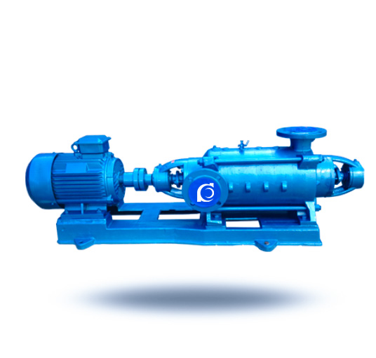
Product Overview
The D Series Single Suction Multistage Clean Water Pump is a high-efficiency multistage centrifugal pump designed for a wide range of applications, featuring stable performance, low noise, long lifespan, and easy installation and maintenance. This pump is primarily used for transporting clean water and other non-corrosive liquids with physical and chemical properties similar to water, making it ideal for industrial, agricultural, and municipal water supply systems.
Model Designation

Main Features
-
Advanced hydraulic design ensures high efficiency and a wide range of operational performance.
-
Low noise operation, suitable for environments requiring long-term continuous operation.
-
Reliable sealing technology, including packing gland seals and mechanical seals, simplifying maintenance.
-
Standard motor coupling allows for flexible installation and use.
Engineering Overview
The D Series pumps are designed using computer-aided design (CAD) and performance optimization technology, with extensive manufacturing experience and a comprehensive testing facility, ensuring stability and reliability under varying operational conditions. All pump bodies are made of corrosion-resistant materials, enhancing the pump’s service life.
Typical Applications
The D Series pumps are widely used in the following fields:
-
Industrial and municipal water supply and drainage
-
High-rise building water supply systems
-
Hot water circulation and boiler feedwater
-
Firefighting pressure boosting systems
-
Irrigation and agricultural watering
-
Food processing, chemical, and pharmaceutical industries
System Configuration
The system consists of several core components to ensure efficient and stable operation:
-
Pump shaft and shaft sleeve
-
Suction casing and intermediate casing
-
Discharge casing and tail cover
-
Efficient impeller and diffuser design
-
Sealing system and bearing components
Components and Supply
The system includes:
-
Suction casing and intermediate casing
-
Diffuser baffle and discharge diffuser
-
Mechanical seals and bearings
-
Motor and drive system
-
Necessary installation accessories and parts
Technical Services
The D Series pumps offer comprehensive technical services to ensure long-term stability for users. Service offerings include:
-
Installation and commissioning
-
Regular maintenance and servicing
-
Operation training and technical support
Operating Conditions
-
Suitable for clean water or liquids with properties similar to water.
-
Maximum liquid temperature: ≤ 110°C.
-
Inlet pressure: less than 0.6 MPa.
-
Bearing lubrication: calcium-based grease.
Service Conditions
-
Fire hydrant systems: Flow rate of 2.5L/S or 5L/S per nozzle, with water column lengths of 7m, 10m, or 13m.
-
Automatic sprinkler systems: Flow rate of 1.0L/S per sprinkler, with sprinkler pressure at 0.1 MPa.
-
Ambient temperature: 5°C to 40°C.
Protection Features
The D Series pumps are equipped with multiple protection features, including:
-
Overload protection
-
Overpressure protection
-
Bearing temperature monitoring
-
Mechanical failure alarm system
Selection Standards
The selection of D Series pumps should be based on the specific application scenario, required flow rate, and pump head requirements. Considerations should also include installation space, maintenance convenience, and the long-term stability of the system.
Installation & Dimensions
Outline Drawing

Performance Data
| 1 | Bearing Cover | 2 | Nut | 3 | Bearing | 4 | Water Deflector Sleeve | 5 | Bearing Bracket | 6 | Shaft Sleeve (A) | 7 | Packing Gland | 8 | Lantern Ring |
| 9 | Suction Casing | 10 | Intermediate Sleeve | 11 | Wear Ring | 12 | Impeller | 13 | Middle Casing | 14 | Diffuser Baffle | 15 | Diffuser Sleeve | 16 | Tension Bolt |
| 17 | Outlet Diffuser | 18 | Balance Ring | 19 | Balance Ring | 20 | Balance Disc | 21 | Discharge Casing | 22 | Tail Cover | 23 | Shaft | 24 | Shaft Sleeve (B) |
Performance Parameters
| Model | Stages | Flow Rate (Q) | Head (m) | Speed (r/min) | Power (kW) | NPSH (m) | Efficiency η (%) | ||
| m³/h | L/s | Shaft Power | Motor Power | ||||||
| 50D8×2 | 2 | 18 | 5 | 19 | 2950 | 1.5 | 2.2 | 2.3 | 62 |
| 50D8×3 | 3 | 18 | 5 | 28.5 | 2950 | 2.25 | 3 | 2.3 | 62 |
| 50D8×4 | 4 | 18 | 5 | 38 | 2950 | 3 | 4 | 2.3 | 62 |
| 50D8×5 | 5 | 18 | 5 | 47.5 | 2950 | 3.75 | 5.5 | 2.3 | 62 |
| 50D8×6 | 6 | 18 | 5 | 57 | 2950 | 4.5 | 5.5 | 2.3 | 62 |
| 50D8×7 | 7 | 18 | 5 | 66.5 | 2950 | 5.25 | 7.5 | 2.3 | 62 |
| 50D8×8 | 8 | 18 | 5 | 76 | 2950 | 6 | 7.5 | 2.3 | 62 |
| 50D8×9 | 9 | 18 | 5 | 85.5 | 2950 | 6.75 | 7.5 | 2.3 | 62 |
| 50D8×10 | 10 | 18 | 5 | 95 | 2950 | 7.5 | 11 | 2.3 | 62 |
| 50D8×11 | 11 | 18 | 5 | 104.5 | 2950 | 8.25 | 11 | 2.3 | 62 |
| 50D8×12 | 12 | 18 | 5 | 114 | 2950 | 9 | 11 | 2.3 | 62 |
| Model | Stages | Flow Rate (Q) | Head (m) | Speed (r/min) | Power (kW) | NPSH (m) | Efficiency η (%) | ||
| m³/h | L/s | Shaft Power | Motor Power | ||||||
| 80D12×2 | 2 | 32.4 | 9 | 22.7 | 2950 | 2.68 | 3 | 2.8 | 75 |
| 80D12×3 | 3 | 32.4 | 9 | 34.05 | 2950 | 4.02 | 5.5 | 2.8 | 75 |
| 80D12×4 | 4 | 32.4 | 9 | 45.4 | 2950 | 5.36 | 7.5 | 2.8 | 75 |
| 80D12×5 | 5 | 32.4 | 9 | 56.75 | 2950 | 6.7 | 7.5 | 2.8 | 75 |
| 80D12×6 | 6 | 32.4 | 9 | 68.1 | 2950 | 8.04 | 11 | 2.8 | 75 |
| 80D12×7 | 7 | 32.4 | 9 | 79.45 | 2950 | 9.38 | 11 | 2.8 | 75 |
| 80D12×8 | 8 | 32.4 | 9 | 90.8 | 2950 | 10.72 | 15 | 2.8 | 75 |
| 80D12×9 | 9 | 32.4 | 9 | 102.15 | 2950 | 11.06 | 15 | 2.8 | 75 |
| 80D12×10 | 10 | 32.4 | 9 | 113.5 | 2950 | 13.4 | 15 | 2.8 | 75 |
| 80D12×11 | 11 | 32.4 | 9 | 124.85 | 2950 | 14.74 | 18.5 | 2.8 | 75 |
| 80D12×12 | 12 | 32.4 | 9 | 136.2 | 2950 | 16.08 | 18.5 | 2.8 | 75 |
| Model | Stages | Flow Rate (Q) | Head (m) | Speed (r/min) | Power (kW) | NPSH (m) | Efficiency η (%) | ||
| m³/h | L/s | Shaft Power | Motor Power | ||||||
| 100D16×2 | 2 | 54 | 15 | 35.2 | 2950 | 7.2 | 11 | 3.3 | 71.5 |
| 100D16×3 | 3 | 54 | 15 | 52.8 | 2950 | 10.8 | 15 | 3.3 | 71.5 |
| 100D16×4 | 4 | 54 | 15 | 70.4 | 2950 | 14.4 | 18.5 | 3.3 | 71.5 |
| 100D16×5 | 5 | 54 | 15 | 88 | 2950 | 18 | 22 | 3.3 | 71.5 |
| 100D16×6 | 6 | 54 | 15 | 105.6 | 2950 | 21.6 | 30 | 3.3 | 71.5 |
| 100D16×7 | 7 | 54 | 15 | 123.2 | 2950 | 25.2 | 30 | 3.3 | 71.5 |
| 100D16×8 | 8 | 54 | 15 | 140.8 | 2950 | 28.8 | 37 | 3.3 | 71.5 |
| 100D16×9 | 9 | 54 | 15 | 158.4 | 2950 | 32.4 | 37 | 3.3 | 71.5 |
| 100D16×10 | 10 | 54 | 15 | 176 | 2950 | 36 | 45 | 3.3 | 71.5 |
| 100D16×11 | 11 | 54 | 15 | 198.6 | 2950 | 39.6 | 55 | 3.3 | 71.5 |
| 100D16×12 | 12 | 54 | 15 | 211.2 | 2950 | 43.2 | 55 | 3.3 | 71.5 |
| Model | Stages | Flow Rate (Q) | Head (m) | Speed (r/min) | Power (kW) | NPSH (m) | Efficiency η (%) | ||
| m³/h | L/s | Shaft Power | Motor Power | ||||||
| 125D25×2 | 2 | 108 | 30 | 40 | 2950 | 15.6 | 18.5 | 4 | 76 |
| 125D25×3 | 3 | 108 | 30 | 60 | 2950 | 23.4 | 30 | 4 | 76 |
| 125D25×4 | 4 | 108 | 30 | 80 | 2950 | 31.2 | 37 | 4 | 76 |
| 125D25×5 | 5 | 108 | 30 | 100 | 2950 | 39 | 45 | 4 | 76 |
| 125D25×6 | 6 | 108 | 30 | 120 | 2950 | 46.8 | 55 | 4 | 76 |
| 125D25×7 | 7 | 108 | 30 | 140 | 2950 | 54.6 | 75 | 4 | 76 |
| 125D25×8 | 8 | 108 | 30 | 160 | 2950 | 62.4 | 75 | 4 | 76 |
| 125D25×9 | 9 | 108 | 30 | 180 | 2950 | 70.3 | 90 | 4 | 76 |
| 125D25×10 | 10 | 108 | 30 | 200 | 2950 | 78 | 90 | 4 | 76 |
| Model | Stages | Flow Rate (Q) | Head (m) | Speed (r/min) | Power (kW) | NPSH (m) | Efficiency η (%) | ||
| m³/h | L/s | Shaft Power | Motor Power | ||||||
| 150D30×2 | 2 | 162 | 45 | 54.6 | 2950 | 31.46 | 37 | 4.1 | 76.6 |
| 150D30×3 | 3 | 162 | 45 | 81.9 | 2950 | 47.19 | 55 | 4.1 | 76.6 |
| 150D30×4 | 4 | 162 | 45 | 109.2 | 2950 | 62.92 | 75 | 4.1 | 76.6 |
| 150D30×5 | 5 | 162 | 45 | 136.5 | 2950 | 78.65 | 90 | 4.1 | 76.6 |
| 150D30×6 | 6 | 162 | 45 | 163.8 | 2950 | 94.38 | 110 | 4.1 | 76.6 |
| 150D30×7 | 7 | 162 | 45 | 191.1 | 2950 | 110.11 | 132 | 4.1 | 76.6 |
| 150D30×8 | 8 | 162 | 45 | 218.4 | 2950 | 125.84 | 160 | 4.1 | 76.6 |
| 150D30×9 | 9 | 162 | 45 | 245.7 | 2950 | 141.57 | 160 | 4.1 | 76.6 |
Installation Diagram

Performance Data(2)
| Model | Number of Stages | L | L1 | L2 | L3 | L4 | L5 | B | B1 | H | H1 | H2 | H3 | H4 | n-φd |
| 50D8×2 | 2 | 960 | 65 | 490 | 730 | 135 | 345 | 355 | 290 | 230 | 160 | 90 | 100 | 25 | 4-φ20 |
| 50D8×3 | 3 | 1163 | 113 | 550 | 815 | 145 | 390 | 360 | 300 | 240 | 160 | 100 | 145 | 25 | 4-φ20 |
| 50D8×4 | 4 | 1141 | 136 | 580 | 890 | 180 | 410 | 360 | 340 | 242 | 160 | 112 | 153 | 25 | 4-φ20 |
| 50D8×5 | 5 | 1274 | 226 | 710 | 1120 | 270 | 485 | 370 | 370 | 242 | 160 | 132 | 183 | 25 | 4-φ20 |
| 50D8×6 | 6 | 1332 | 226 | 710 | 1120 | 270 | 485 | 370 | 370 | 242 | 160 | 132 | 183 | 25 | 4-φ20 |
| 50D8×7 | 7 | 1390 | 226 | 710 | 1120 | 270 | 485 | 370 | 370 | 242 | 160 | 132 | 183 | 25 | 4-φ20 |
| 50D8×8 | 8 | 1448 | 310 | 770 | 1230 | 300 | 485 | 370 | 370 | 242 | 160 | 132 | 183 | 25 | 4-φ20 |
| 50D8×9 | 9 | 1508 | 310 | 770 | 1230 | 300 | 485 | 370 | 370 | 242 | 160 | 132 | 183 | 25 | 4-φ20 |
| 50D8×10 | 10 | 1689 | 362 | 949 | 1515 | 420 | 610 | 370 | 405 | 255 | 160 | 160 | 225 | 25 | 4-φ20 |
| 50D8×11 | 11 | 1747 | 362 | 940 | 1515 | 420 | 610 | 370 | 405 | 255 | 160 | 160 | 225 | 25 | 4-φ20 |
| 50D8×12 | 12 | 1805 | 362 | 940 | 1515 | 420 | 610 | 370 | 405 | 255 | 160 | 160 | 225 | 25 | 4-φ20 |
| Model | Number of Stages | L | L1 | L2 | L3 | L4 | L5 | B | B1 | H | H1 | H2 | H3 | H4 | n-φd |
| 80D12×2 | 2 | 1139 | 121 | 610 | 860 | 130 | 390 | 410 | 300 | 245 | 210 | 100 | 145 | 25 | 4-φ20 |
| 80D12×3 | 3 | 1304 | 232 | 770 | 1130 | 235 | 485 | 410 | 365 | 247 | 210 | 132 | 183 | 25 | 4-φ20 |
| 80D12×4 | 4 | 1374 | 232 | 770 | 1130 | 235 | 485 | 410 | 365 | 247 | 210 | 132 | 183 | 25 | 4-φ20 |
| 80D12×5 | 5 | 1444 | 232 | 770 | 1130 | 235 | 485 | 410 | 365 | 247 | 210 | 132 | 183 | 25 | 4-φ20 |
| 80D12×6 | 6 | 1639 | 273 | 990 | 1385 | 230 | 610 | 410 | 410 | 260 | 210 | 160 | 225 | 25 | 4-φ20 |
| 80D12×7 | 7 | 1709 | 273 | 990 | 3185 | 230 | 610 | 410 | 410 | 260 | 210 | 160 | 225 | 25 | 4-φ20 |
| 80D12×8 | 8 | 1779 | 403 | 1020 | 1600 | 415 | 610 | 410 | 410 | 260 | 210 | 160 | 225 | 25 | 4-φ20 |
| 80D12×9 | 9 | 1849 | 403 | 1020 | 1600 | 415 | 610 | 410 | 410 | 260 | 210 | 160 | 225 | 25 | 4-φ20 |
| 80D12×10 | 10 | 1919 | 403 | 1020 | 1600 | 415 | 610 | 410 | 410 | 260 | 210 | 160 | 225 | 25 | 4-φ20 |
| 80D12×11 | 11 | 2034 | 471 | 1110 | 1775 | 480 | 655 | 410 | 410 | 260 | 210 | 160 | 225 | 25 | 4-φ20 |
| 80D12×12 | 2104 | 471 | 1110 | 1775 | 480 | 655 | 410 | 410 | 260 | 210 | 160 | 225 | 25 | 4-φ20 | |
| Model | Number of Stages | L | L1 | L2 | L3 | L4 | L5 | B | B1 | H | H1 | H2 | H3 | H4 | n-φd |
| 100D16×2 | 2 | 1395 | 131 | 785 | 1175 | 225 | 615 | 450 | 450 | 280 | 220 | 160 | 225 | 30 | 4-φ20 |
| 100D16×3 | 3 | 1475 | 131 | 785 | 1175 | 225 | 615 | 450 | 450 | 280 | 220 | 160 | 225 | 30 | 4-φ20 |
| 100D16×4 | 4 | 1600 | 191 | 865 | 1300 | 245 | 660 | 450 | 450 | 280 | 220 | 160 | 225 | 30 | 4-φ20 |
| 100D16×5 | 5 | 1705 | 231 | 910 | 1380 | 285 | 695 | 450 | 450 | 300 | 220 | 180 | 250 | 30 | 4-φ20 |
| 100D16×6 | 6 | 1890 | 292 | 1015 | 1620 | 385 | 790 | 485 | 485 | 310 | 220 | 200 | 275 | 35 | 4-φ20 |
| 100D16×7 | 7 | 1970 | 292 | 1015 | 1620 | 385 | 790 | 485 | 485 | 310 | 220 | 200 | 275 | 35 | 4-φ20 |
| 100D16×8 | 8 | 2050 | 372 | 1095 | 1780 | 465 | 790 | 485 | 485 | 310 | 220 | 200 | 275 | 35 | 4-φ20 |
| 100D16×9 | 9 | 2130 | 372 | 1095 | 1780 | 465 | 790 | 485 | 485 | 310 | 220 | 200 | 275 | 35 | 4-φ20 |
| 100D16×10 | 10 | 2250 | 433 | 1175 | 1885 | 485 | 830 | 450 | 515 | 335 | 220 | 225 | 305 | 35 | 4-φ20 |
| 100D16×11 | 11 | 2445 | 491 | 1325 | 2150 | 590 | 945 | 455 | 580 | 360 | 220 | 250 | 325 | 35 | 4-φ20 |
| 100D16×12 | 12 | 2525 | 491 | 1325 | 2150 | 590 | 945 | 455 | 580 | 360 | 220 | 250 | 325 | 35 | 4-φ20 |
| Model | Number of Stages | L | L1 | L2 | L3 | L4 | L5 | B | B1 | H | H1 | H2 | H3 | H4 | n-φd |
| 125D25×2 | 2 | 1619 | 151 | 855 | 1230 | 185 | 660 | 530 | 420 | 330 | 270 | 160 | 225 | 40 | 4-φ24 |
| 125D25×3 | 3 | 1849 | 225.5 | 980 | 1510 | 310 | 790 | 530 | 485 | 330 | 270 | 200 | 275 | 40 | 4-φ24 |
| 125D25×4 | 4 | 1949 | 225.5 | 980 | 1510 | 310 | 790 | 530 | 485 | 330 | 270 | 200 | 275 | 40 | 4-φ24 |
| 125D25×5 | 5 | 2089 | 300 | 1075 | 1635 | 335 | 830 | 540 | 540 | 345 | 270 | 225 | 305 | 40 | 4-φ24 |
| 125D25×6 | 6 | 2304 | 351.5 | 1190 | 1835 | 385 | 945 | 540 | 590 | 370 | 270 | 250 | 325 | 40 | 4-φ24 |
| 125D25×7 | 7 | 2486 | 627 | 1510 | 2115 | 310 | 1018 | 540 | 640 | 400 | 270 | 280 | 360 | 40 | 4-φ24 |
| 125D25×8 | 8 | 2586 | 627 | 1510 | 2115 | 310 | 1018 | 540 | 640 | 400 | 270 | 280 | 360 | 40 | 4-φ24 |
| 125D25×9 | 9 | 2736 | 779 | 1680 | 2370 | 360 | 1068 | 540 | 640 | 400 | 270 | 280 | 360 | 40 | 4-φ24 |
| 125D25×10 | 10 | 2836 | 779 | 1680 | 2370 | 360 | 1068 | 540 | 640 | 400 | 270 | 280 | 360 | 40 | 4-φ24 |
| Model | Number of Stages | L | L1 | L2 | L3 | L4 | L5 | B | B1 | H | H1 | H2 | H3 | H4 | n-φd |
| 150D30×2 | 2 | 1859 | 193 | 975 | 1410 | 205 | 793 | 600 | 500 | 380 | 320 | 200 | 275 | 45 | 4-φ24 |
| 150D30×3 | 3 | 2129 | 249 | 1120 | 1650 | 265 | 948 | 600 | 600 | 380 | 320 | 250 | 325 | 45 | 4-φ24 |
| 150D30×4 | 4 | 2314 | 306 | 1210 | 1835 | 325 | 1018 | 600 | 650 | 390 | 320 | 280 | 360 | 45 | 4-φ24 |
| 150D30×5 | 5 | 2479 | 365 | 1290 | 2000 | 380 | 1068 | 600 | 650 | 400 | 320 | 280 | 360 | 45 | 4-φ24 |
| 150D30×6 | 6 | / | / | / | / | / | / | / | / | / | / | / | / | / | / |
| 150D30×7 | 7 | / | / | / | / | / | / | / | / | / | / | / | / | / | / |
| 150D30×8 | 8 | / | / | / | / | / | / | / | / | / | / | / | / | / | / |
| 150D30×9 | 9 | / | / | / | / | / | / | / | / | / | / | / | / | / | / |
Outline Drawing(2)

Performance Data(3)
| Dimensions | Suction Flange | Discharge Flange | ||||||
| Model | Dg | Do | D | n-do | Dg | Do | D | n-do |
| 50D8 | 75 | 150 | 185 | 4-φ18 | 50 | 125 | 160 | 4-φ18 |
| 80D12 | 80 | 150 | 185 | 4-φ18 | 80 | 160 | 195 | 4-φ18 |
| 100D16 | 100 | 170 | 205 | 4-φ18 | 100 | 180 | 215 | 8-φ18 |
| 125D25 | 125 | 200 | 235 | 8-φ18 | 125 | 210 | 245 | 8-φ18 |
| 150D30 | 150 | 225 | 260 | 8-φ18 | 150 | 240 | 280 | 8-φ18 |
Pump Installation & Performance
Calculation of pump head H:

n the formula:
-
P1: Inlet pressure of the pump (MPa)
-
P2: Outlet pressure of the pump (MPa)
-
Z1: Vertical distance from the inlet pressure gauge to the pump shaft center (m)
-
Z2: Vertical distance from the outlet pressure gauge to the pump shaft center (m)
-
V1: Flow velocity at the inlet pressure measuring point (m/s)
-
V2: Flow velocity at the outlet pressure measuring point (m/s)
-
ρ: Liquid density (kg/m³)
-
g: Gravitational acceleration (9.8 m/s²)
Calculation of Pump Installation Height (Hg)
(Installation height refers to the vertical distance from the pump shaft centerline to the inlet liquid level.)
Hg ≤ P0 – [NPSH] – P’ – Δh – 0.5 (m)
In the formula:
-
P0: Atmospheric pressure (or absolute pressure at the inlet liquid level) (m water column)
-
[NPSH]: Required NPSH (Net Positive Suction Head) of the pump (m)
-
P’: Vapor pressure of the pumped liquid (m water column)
-
Δh: Hydraulic loss in the inlet pipeline (m)
Note:
-
When the calculated value of Hg is positive, it indicates that the pump shaft center is above the inlet liquid level.
-
When the calculated value is negative, it indicates that the pump is operating under flooded suction conditios.
Calculated according to the following formulas:

Operating Manual
(I) Installation:
-
Preparations before installation:
-
(1) Inspect the pump and motor.
-
(2) Prepare tools and lifting equipment.
-
(3) Verify the foundation of the unit.
-
-
Installation procedure:
-
(1) If the complete pump set is delivered to the site with the baseplate and motor pre-mounted and leveled, the pump and motor do not need to be removed.
-
(2) Place the baseplate on the foundation. Insert wedge-shaped shims near the foundation bolts and raise the baseplate by about 20–40 mm to allow for grouting after leveling.
-
(3) Use a level gauge to check the levelness of the baseplate. After leveling, tighten the foundation nuts and grout the baseplate with cement mortar.
-
(4) After the cement has cured for 3–4 days, recheck the levelness.
-
(5) Clean any dirt from the supporting surfaces of the baseplate, pump feet, and motor feet, then place the pump and motor on the baseplate.
-
(6) Adjust the pump shaft to ensure it is level. After leveling, tighten the nuts to prevent movement. Once the adjustment is complete, install the motor. If the level is incorrect, insert steel shims and leave an appropriate clearance between the pump and coupling.
-
(7) Place a straightedge on the coupling to check if the pump shaft centerline aligns with the motor shaft centerline. If they do not align, insert thin shims under the motor or pump feet so the two coupling faces are flush with the straightedge. Then, remove the thin shims and replace them with a machined solid steel plate, and recheck the installation condition.
-
To check the installation accuracy, use a feeler gauge at several positions around the coupling faces to measure the gap. The difference between the maximum and minimum gap should not exceed 0.3 mm, and the difference between the centerlines at the two ends (up/down or left/right) should not exceed 0.1 mm.
-
(II) Start-up & Shutdown:
-
Start-up:
-
(1) Wipe off the oil applied on the shaft and other lubricated parts.
-
(2) Clean the bearings and oil chamber with gasoline and wipe them dry with cotton yarn.
-
(3) Fill the bearing housing with calcium-based grease.
-
(4) After successful test running, check whether the motor’s rotation direction is correct. Prevent reverse rotation of the pump as it could loosen nuts, and then start the motor.
-
(5) Fill the pump with water or prime it.
-
(6) Close the valve and pressure gauge cock on the discharge pipeline.
-
(7) Once the above steps are complete, start the motor and open the pressure gauge cock.
-
(8) After the pump reaches normal speed and the pressure gauge shows appropriate pressure, open the vacuum gauge cock and gradually open the gate valve on the discharge pipeline until the required pressure is reached.
-
-
Shutdown:
-
(9) When stopping the pump, slowly close the gate valve on the discharge pipeline, close the vacuum gauge cock, stop the motor, and finally close the pressure gauge cock.
-
(10) If the pump is out of service for an extended period, disassemble it, wipe off any water on the pump parts, and apply anti-rust oil to the sliding surfaces for proper storage.
-
(III) Operation:
-
Monitoring:
-
(1) Monitor the temperature of the pump bearings. It should not exceed the ambient temperature by more than 35°C, and the maximum temperature should not exceed 75°C.
-
(2) Normal leakage in the stuffing box should not exceed about 15 ml per minute. The packing gland should be adjusted as necessary to maintain proper tightness.
-
(3) Periodically check the coupling and monitor the motor bearing temperature rise.
-
(4) If any noise or abnormal sounds occur during operation, immediately stop the pump and investigate the cause.
-
OEM & Custom
We offer OEM/ODM customization for materials (cast iron, stainless steel, duplex steel), motor voltage (220V/415V/460V), and installation configuration. Explosion-proof motors, control panels, and base-mounted assemblies are available. All products are tested to ISO9001 and CE standards, ensuring high performance and reliability for export projects.
FAQs
- Q: What is the main application of the D series pump?
A: It is widely used for industrial and municipal water supply, boiler feed, and pressure boosting for clean water systems. - Q: What’s the maximum temperature of the liquid?
A: The D pump can handle liquids up to 80°C; special versions can operate up to 120°C. - Q: Can it be used for slightly corrosive liquids?
A: Yes, with stainless steel wetted parts or optional mechanical seals for specific fluids. - Q: What is the maximum head?
A: Depending on the model and stage number, the pump head can reach up to 232 meters. - Q: What are the maintenance requirements?
A: Regular lubrication and seal inspection; no complex maintenance procedures are required. - Q: Do you support OEM voltage customization?
A: Yes, we provide custom voltages and control systems for export markets. - Q: Which countries import this pump?
A: The D series is exported to Southeast Asia, Africa, and South America for industrial and municipal water projects.