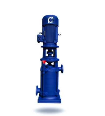
DL/DLR Vertical Multistage Centrifugal Pump High Efficiency
DL/DLR Vertical Multistage Centrifugal Pump | Low-speed boosting for stable constant-pressure duty
- Constant-pressure boosting: High-rise supply, fire boosting, sprinkler/water-curtain systems.
- Vertical multistage design: Compact footprint with stable high-head build-up.
- Low-speed operation: Smooth running with controlled vibration for continuous duty.
- Service-ready sealing: Mechanical seal arrangement with straightforward maintenance access.