Product Overview
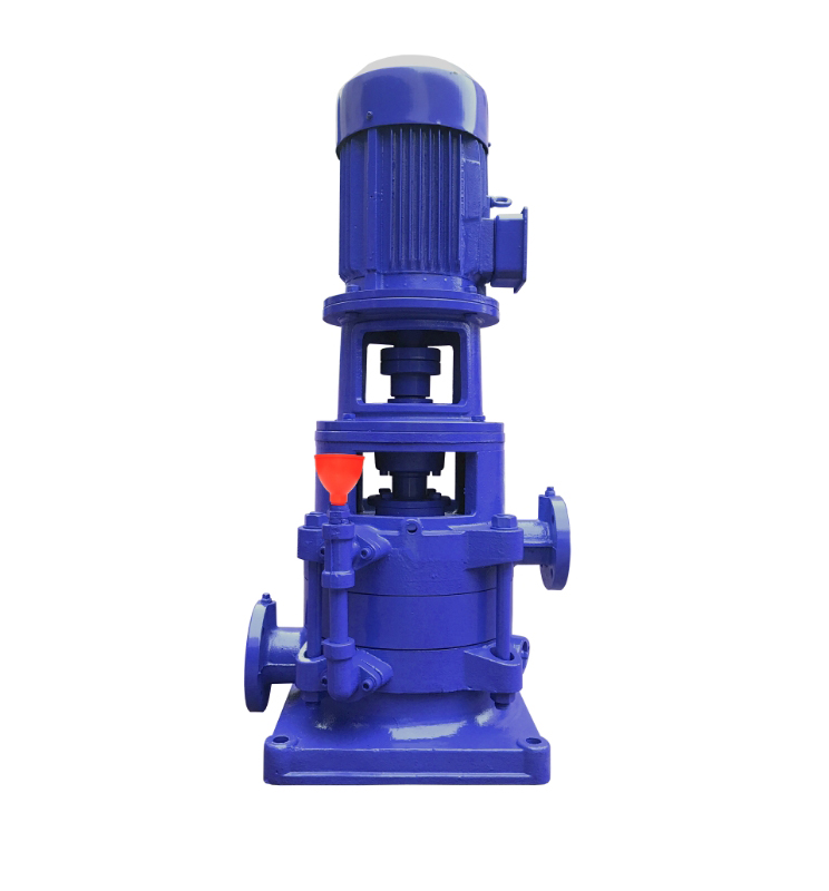
The DL Vertical Multistage Clean Water Pump (Low-Speed Model, n = 1450 r/min) is a vertical multistage pump unit developed for continuous operation in high-rise building water supply and fire protection systems. Featuring a multistage hydraulic configuration with impellers arranged in series, it delivers high head output and is well-suited for applications requiring high operational stability, system reliability, and efficient pump room space utilization.
This pump series is designed to convey non-corrosive liquids with physical and chemical properties similar to clean water, free of hard solid particles, and capable of supporting long-term reliable operation in building water and fire systems.
Model Designation


Performance Data
|
No.
|
Name
|
Material / Model
|
No.
|
Name
|
Material / Model
|
|
1
|
Motor
|
Y Series (V5) 4-pole
|
12
|
Discharge Section
|
HT200
|
|
2
|
Coupling
|
HT200
|
13
|
Balance Sleeve
|
HT200
|
|
3
|
Elastic Block
|
Rubber
|
14
|
Balance Drum
|
HT200
|
|
4
|
Bearing Gland
|
HT200
|
15
|
Final Stage Diffuser
|
HT200
|
|
5
|
Bearing Nut
|
45 Steel
|
16
|
Intermediate Section
|
HT200
|
|
6
|
Bearing Housing
|
HT200
|
17
|
Diffuser
|
HT200
|
|
7
|
Bearing
|
180 Series
|
18
|
Impeller
|
HT200
|
|
8
|
Water-block Sleeve
|
45 Steel
|
19
|
Suction Section
|
HT200
|
|
9
|
Asbestos Gland
|
HT200
|
20
|
Lower Shaft Sleeve
|
45 Steel
|
|
10
|
Asbestos
|
Asbestos
|
21
|
Lower Bearing
|
Copper Alloy
|
|
11
|
Stuffing Box Body
|
HT200
|
22
|
Shaft
|
45 Steel / 2Cr13
|
| Note: 1. This pump type can be customized as a hot water model. 2. The asbestos packing can be replaced with a mechanical seal. 3. Please specify these requirements when ordering; pricing will be adjusted accordingly. |
|||||
Performance Parameters
|
Model
|
Stages
|
Speed
|
Efficiency
|
NPSHr
|
Flow
|
Head
|
Power
|
Weight
|
|
r/min
|
%
|
M
|
m3/h
|
M
|
kw
|
Kg
|
||
|
40DL6.2-11.2*2
|
2
|
1450
|
40
|
3.19
|
6.2
|
23.6
|
1.5
|
152
|
|
40DL6.2-11.2*3
|
3
|
1450
|
40
|
3.19
|
6.2
|
35.4
|
2.2
|
169
|
|
40DL6.2-11.2*4
|
4
|
1450
|
40
|
3.19
|
6.2
|
47.2
|
3
|
186
|
|
40DL6.2-11.2*5
|
5
|
1450
|
40
|
3.19
|
6.2
|
59
|
4
|
203
|
|
40DL6.2-11.2*6
|
6
|
1450
|
40
|
3.19
|
6.2
|
70.8
|
4
|
220
|
|
40DL6.2-11.2*7
|
7
|
1450
|
40
|
3.19
|
6.2
|
82.6
|
5.5
|
237
|
|
40DL6.2-11.2*8
|
8
|
1450
|
40
|
3.19
|
6.2
|
94.4
|
5.5
|
254
|
|
40DL6.2-11.2*9
|
9
|
1450
|
40
|
3.19
|
6.2
|
106.2
|
7.5
|
271
|
|
40DL6.2-11.2*10
|
10
|
1450
|
40
|
3.19
|
6.2
|
118
|
7.5
|
/
|
|
40DL6.2-11.2*11
|
11
|
1450
|
40
|
3.19
|
6.2
|
129.8
|
7.5
|
/
|
|
40DL6.2-11.2*12
|
12
|
1450
|
40
|
3.19
|
6.2
|
141.6
|
11
|
/
|
|
Model
|
Stages
|
Speed
|
Efficiency
|
NPSHr
|
Flow
|
Head
|
Power
|
Weight
|
|
r/min
|
%
|
M
|
m3/h
|
M
|
kw
|
Kg
|
||
|
50DL12.6-12.2*2
|
2
|
1450
|
54
|
2.66
|
12.6
|
24.4
|
3
|
15.3
|
|
50DL12.6-12.2*3
|
3
|
1450
|
54
|
2.66
|
12.6
|
36.6
|
3
|
18
|
|
50DL12.6-12.2*4
|
4
|
1450
|
54
|
2.66
|
12.6
|
48.8
|
4
|
23.1
|
|
50DL12.6-12.2*5
|
5
|
1450
|
54
|
2.66
|
12.6
|
61
|
5.5
|
33
|
|
50DL12.6-12.2*6
|
6
|
1450
|
54
|
2.66
|
12.6
|
73.2
|
5.5
|
24
|
|
50DL12.6-12.2*7
|
7
|
1450
|
54
|
2.66
|
12.6
|
85.4
|
7.5
|
15
|
|
50DL12.6-12.2*8
|
8
|
1450
|
54
|
2.66
|
12.6
|
97.6
|
7.5
|
18
|
|
50DL12.6-12.2*9
|
9
|
1450
|
54
|
2.66
|
12.6
|
109.8
|
11
|
22
|
|
50DL12.6-12.2*10
|
10
|
1450
|
54
|
2.66
|
12.6
|
122
|
11
|
/
|
|
Model
|
Stages
|
Speed
|
Efficiency
|
NPSHr
|
Flow
|
Head
|
Power
|
Weight
|
|
r/min
|
%
|
M
|
m3/h
|
M
|
kw
|
Kg
|
||
|
65DL30-16*2
|
2
|
1450
|
62
|
2.82
|
30
|
32
|
5.5
|
349
|
|
65DL30-16*3
|
3
|
1450
|
62
|
2.82
|
30
|
48
|
7.5
|
390
|
|
65DL30-16*4
|
4
|
1450
|
62
|
2.82
|
30
|
64
|
11
|
460
|
|
65DL30-16*5
|
5
|
1450
|
62
|
2.82
|
30
|
80
|
15
|
509
|
|
65DL30-16*6
|
6
|
1450
|
62
|
2.82
|
30
|
96
|
15
|
537
|
|
65DL30-16*7
|
7
|
1450
|
62
|
2.82
|
30
|
112
|
18.5
|
603
|
|
65DL30-16*8
|
8
|
1450
|
62
|
2.82
|
30
|
128
|
22
|
639
|
|
65DL30-16*9
|
9
|
1450
|
62
|
2.82
|
30
|
144
|
22
|
667
|
|
65DL30-16*10
|
10
|
1450
|
62
|
2.82
|
30
|
160
|
30
|
720
|
|
Model
|
Stages
|
Speed
|
Efficiency
|
NPSHr
|
Flow
|
Head
|
Power
|
Weight
|
|
r/min
|
%
|
M
|
m3/h
|
M
|
kw
|
Kg
|
||
|
80DL50-20*2
|
2
|
1450
|
70
|
2.5
|
50
|
40
|
11
|
461
|
|
80DL50-20*3
|
3
|
1450
|
70
|
2.5
|
50
|
60
|
15
|
522
|
|
80DL50-20*4
|
4
|
1450
|
70
|
2.5
|
50
|
80
|
22
|
608
|
|
80DL50-20*5
|
5
|
1450
|
70
|
2.5
|
50
|
100
|
30
|
728
|
|
80DL50-20*6
|
6
|
1450
|
70
|
2.5
|
50
|
120
|
30
|
768
|
|
80DL50-20*7
|
7
|
1450
|
70
|
2.5
|
50
|
140
|
37
|
822
|
|
80DL50-20*8
|
8
|
1450
|
70
|
2.5
|
50
|
160
|
45
|
898
|
|
80DL50-20*9
|
9
|
1450
|
70
|
2.5
|
50
|
180
|
45
|
938
|
|
80DL50-20*10
|
10
|
1450
|
70
|
2.5
|
50
|
200
|
55
|
/
|
|
Model
|
Stages
|
Speed
|
Efficiency
|
NPSHr
|
Flow
|
Head
|
Power
|
Weight
|
|
r/min
|
%
|
M
|
m3/h
|
M
|
kw
|
Kg
|
||
|
100DL72-20*2
|
2
|
1450
|
72
|
2.8
|
72
|
40
|
15
|
521
|
|
100DL72-20*3
|
3
|
1450
|
72
|
2.8
|
72
|
60
|
18.5
|
599
|
|
100DL72-20*4
|
4
|
1450
|
72
|
2.8
|
72
|
80
|
30
|
727
|
|
100DL72-20*5
|
5
|
1450
|
72
|
2.8
|
72
|
100
|
37
|
781
|
|
100DL72-20*6
|
6
|
1450
|
72
|
2.8
|
72
|
120
|
37
|
821
|
|
100DL72-20*7
|
7
|
1450
|
72
|
2.8
|
72
|
140
|
45
|
897
|
|
100DL72-20*8
|
8
|
1450
|
72
|
2.8
|
72
|
160
|
55
|
1044
|
|
100DL72-20*9
|
9
|
1450
|
72
|
2.8
|
72
|
180
|
55
|
1084
|
|
100DL72-20*10
|
10
|
1450
|
72
|
2.8
|
72
|
200
|
75
|
/
|
|
Model
|
Stages
|
Speed
|
Efficiency
|
NPSHr
|
Flow
|
Head
|
Power
|
Weight
|
|
r/min
|
%
|
M
|
m3/h
|
M
|
kw
|
Kg
|
||
|
100DL100-20*2
|
2
|
1450
|
72
|
3.5
|
100
|
40
|
18.5
|
554
|
|
100DL100-20*3
|
3
|
1450
|
72
|
3.5
|
100
|
60
|
30
|
687
|
|
100DL100-20*4
|
4
|
1450
|
72
|
3.5
|
100
|
80
|
37
|
746
|
|
100DL100-20*5
|
5
|
1450
|
72
|
3.5
|
100
|
100
|
45
|
827
|
|
100DL100-20*6
|
6
|
1450
|
72
|
3.5
|
100
|
120
|
55
|
979
|
|
100DL100-20*7
|
7
|
1450
|
72
|
3.5
|
100
|
140
|
75
|
1159
|
|
100DL100-20*8
|
8
|
1450
|
72
|
3.5
|
100
|
160
|
75
|
1204
|
|
100DL100-20*9
|
9
|
1450
|
72
|
3.5
|
100
|
180
|
90
|
1354
|
|
100DL100-20*10
|
10
|
1450
|
72
|
3.5
|
100
|
200
|
90
|
/
|
|
Model
|
Stages
|
Speed
|
Efficiency
|
NPSHr
|
Flow
|
Head
|
Power
|
Weight
|
|
r/min
|
%
|
M
|
m3/h
|
M
|
kw
|
Kg
|
||
|
150DL150-20*2
|
2
|
1450
|
80
|
2.8
|
150
|
40
|
30
|
569
|
|
150DL150-20*3
|
3
|
1450
|
80
|
2.8
|
150
|
60
|
37
|
707
|
|
150DL150-20*4
|
4
|
1450
|
80
|
2.8
|
150
|
80
|
45
|
771
|
|
150DL150-20*5
|
5
|
1450
|
80
|
2.8
|
150
|
100
|
55
|
857
|
|
150DL150-20*6
|
6
|
1450
|
80
|
2.8
|
150
|
120
|
75
|
1060
|
|
150DL150-20*7
|
7
|
1450
|
80
|
2.8
|
150
|
140
|
75
|
1245
|
|
150DL150-20*8
|
8
|
1450
|
80
|
2.8
|
150
|
160
|
90
|
1295
|
|
Model
|
Stages
|
Speed
|
Efficiency
|
NPSHr
|
Flow
|
Head
|
Power
|
Weight
|
|
r/min
|
%
|
M
|
m3/h
|
M
|
kw
|
Kg
|
||
|
150DL160-25*2
|
2
|
1450
|
76
|
3.5
|
160
|
50
|
37
|
873
|
|
150DL160-25*3
|
3
|
1450
|
76
|
3.5
|
160
|
75
|
55
|
1086
|
|
150DL160-25*4
|
4
|
1450
|
76
|
3.5
|
160
|
100
|
75
|
1291
|
|
150DL160-25*5
|
5
|
1450
|
76
|
3.5
|
160
|
125
|
90
|
1466
|
|
150DL160-25*6
|
6
|
1450
|
76
|
3.5
|
160
|
150
|
110
|
1633
|
|
150DL160-25*7
|
7
|
1450
|
76
|
3.5
|
160
|
175
|
132
|
1803
|
|
150DL160-25*8
|
8
|
1450
|
76
|
3.5
|
160
|
200
|
132
|
1873
|
|
150DL160-25*9
|
9
|
1450
|
76
|
3.5
|
160
|
225
|
160
|
2003
|
|
Model
|
Stages
|
Speed
|
Efficiency
|
NPSHr
|
Flow
|
Head
|
Power
|
Weight
|
|
r/min
|
%
|
M
|
m3/h
|
M
|
kw
|
Kg
|
||
|
200DL300-20*2
|
2
|
1450
|
79
|
5
|
300
|
40
|
55
|
983
|
|
200DL300-20*3
|
3
|
1450
|
79
|
5
|
300
|
60
|
75
|
1196
|
|
200DL300-20*4
|
4
|
1450
|
79
|
5
|
300
|
80
|
110
|
1845
|
|
200DL300-20*5
|
5
|
1450
|
79
|
5
|
300
|
100
|
132
|
1975
|
|
200DL300-20*6
|
6
|
1450
|
79
|
5
|
300
|
120
|
160
|
2120
|
|
200DL288-30*2
|
2
|
1450
|
77.9
|
3.7
|
288
|
60
|
75
|
/
|
|
200DL288-30*3
|
3
|
1450
|
77.9
|
3.7
|
288
|
90
|
110
|
/
|
|
200DL288-30*4
|
4
|
1450
|
77.9
|
3.7
|
288
|
120
|
132
|
/
|
|
200DL288-30*5
|
5
|
1450
|
77.9
|
3.7
|
288
|
150
|
160
|
/
|
|
200DL288-30*6
|
6
|
1450
|
77.9
|
3.7
|
288
|
180
|
200
|
/
|
Installation Diagram

Performance Data(2)
|
Model |
Stages
|
L
|
H
|
H1
|
H2
|
B
|
b
|
n-φd
|
Inlet Flange
|
Outlet Flange
|
||||||
|
Dj
|
Djn
|
Dj2
|
n-dj
|
Dc
|
Dcn
|
Dc2
|
n-φdc
|
|||||||||
|
40DL6.2-11.2
|
2
|
225
|
938
|
112
|
170
|
350
|
300
|
4-φ18
|
150
|
40
|
110
|
4-φ18
|
150
|
40
|
110
|
4-φ18
|
|
40DL6.2-11.2
|
3
|
225
|
1043
|
112
|
230
|
350
|
300
|
4-φ18
|
150
|
40
|
110
|
4-φ18
|
150
|
40
|
110
|
4-φ18
|
|
40DL6.2-11.2
|
4
|
225
|
1103
|
112
|
290
|
350
|
300
|
4-φ18
|
150
|
40
|
110
|
4-φ18
|
150
|
40
|
110
|
4-φ18
|
|
40DL6.2-11.2
|
5
|
225
|
1183
|
112
|
350
|
350
|
300
|
4-φ18
|
150
|
40
|
110
|
4-φ18
|
150
|
40
|
110
|
4-φ18
|
|
40DL6.2-11.2
|
6
|
225
|
1243
|
112
|
410
|
350
|
300
|
4-φ18
|
150
|
40
|
110
|
4-φ18
|
150
|
40
|
110
|
4-φ18
|
|
40DL6.2-11.2
|
7
|
225
|
1378
|
112
|
470
|
350
|
300
|
4-φ18
|
150
|
40
|
110
|
4-φ18
|
150
|
40
|
110
|
4-φ18
|
|
40DL6.2-11.2
|
8
|
225
|
1438
|
112
|
530
|
350
|
300
|
4-φ18
|
150
|
40
|
110
|
4-φ18
|
150
|
40
|
110
|
4-φ18
|
|
40DL6.2-11.2
|
9
|
225
|
1538
|
112
|
590
|
350
|
300
|
4-φ18
|
150
|
40
|
110
|
4-φ18
|
150
|
40
|
110
|
4-φ18
|
|
40DL6.2-11.2
|
10
|
225
|
1598
|
112
|
650
|
350
|
300
|
4-φ18
|
150
|
40
|
110
|
4-φ18
|
150
|
40
|
110
|
4-φ18
|
|
40DL6.2-11.2
|
11
|
225
|
1658
|
112
|
710
|
350
|
300
|
4-φ18
|
150
|
40
|
110
|
4-φ18
|
150
|
40
|
110
|
4-φ18
|
|
40DL6.2-11.2
|
12
|
225
|
1803
|
112
|
770
|
350
|
300
|
4-φ18
|
150
|
40
|
110
|
4-φ18
|
150
|
40
|
110
|
4-φ18
|
|
Model |
Stages
|
L
|
H
|
H1
|
H2
|
B
|
b
|
n-φd
|
Inlet Flange
|
Outlet Flange
|
||||||
|
Dj
|
Djn
|
Dj2
|
n-dj
|
Dc
|
Dcn
|
Dc2
|
n-φdc
|
|||||||||
|
50DL12.6-12.2
|
2
|
220
|
1084
|
104
|
189
|
360
|
305
|
4-φ18
|
165
|
50
|
125
|
4-φ18
|
150
|
40
|
110
|
4-φ18
|
|
50DL12.6-12.2
|
3
|
220
|
1152
|
104
|
257
|
360
|
305
|
4-φ18
|
165
|
50
|
125
|
4-φ18
|
150
|
40
|
110
|
4-φ18
|
|
50DL12.6-12.2
|
4
|
220
|
1240
|
104
|
325
|
360
|
305
|
4-φ18
|
165
|
50
|
125
|
4-φ18
|
150
|
40
|
110
|
4-φ18
|
|
50DL12.6-12.2
|
5
|
220
|
1383
|
104
|
393
|
360
|
305
|
4-φ18
|
165
|
50
|
125
|
4-φ18
|
150
|
40
|
110
|
4-φ18
|
|
50DL12.6-12.2
|
6
|
220
|
1451
|
104
|
461
|
360
|
305
|
4-φ18
|
165
|
50
|
125
|
4-φ18
|
150
|
40
|
110
|
4-φ18
|
|
50DL12.6-12.2
|
7
|
220
|
1559
|
104
|
529
|
360
|
305
|
4-φ18
|
165
|
50
|
125
|
4-φ18
|
150
|
40
|
110
|
4-φ18
|
|
50DL12.6-12.2
|
8
|
220
|
1629
|
104
|
597
|
360
|
305
|
4-φ18
|
165
|
50
|
125
|
4-φ18
|
150
|
40
|
110
|
4-φ18
|
|
50DL12.6-12.2
|
9
|
220
|
1780
|
104
|
665
|
360
|
305
|
4-φ18
|
165
|
50
|
125
|
4-φ18
|
150
|
40
|
110
|
4-φ18
|
|
50DL12.6-12.2
|
10
|
220
|
1848
|
104
|
733
|
360
|
305
|
4-φ18
|
165
|
50
|
125
|
4-φ18
|
150
|
40
|
110
|
4-φ18
|
|
Model |
Stages
|
L
|
H
|
H1
|
H2
|
B
|
b
|
n-φd
|
Inlet Flange
|
Outlet Flange
|
||||||
|
Dj
|
Djn
|
Dj2
|
n-dj
|
Dc
|
Dcn
|
Dc2
|
n-φdc
|
|||||||||
|
65DL30-16
|
2
|
260
|
1306
|
170
|
199
|
430
|
370
|
4-φ24
|
185
|
65
|
145
|
4-φ18
|
165
|
50
|
125
|
4-φ18
|
|
65DL30-16
|
3
|
260
|
1426
|
170
|
279
|
430
|
370
|
4-φ24
|
185
|
65
|
145
|
4-φ18
|
165
|
50
|
125
|
4-φ18
|
|
65DL30-16
|
4
|
260
|
1591
|
170
|
359
|
430
|
370
|
4-φ24
|
185
|
65
|
145
|
4-φ18
|
165
|
50
|
125
|
4-φ18
|
|
65DL30-16
|
5
|
260
|
1716
|
170
|
439
|
430
|
370
|
4-φ24
|
185
|
65
|
145
|
4-φ18
|
165
|
50
|
125
|
4-φ18
|
|
65DL30-16
|
6
|
260
|
1796
|
170
|
519
|
430
|
370
|
4-φ24
|
185
|
65
|
145
|
4-φ18
|
165
|
50
|
125
|
4-φ18
|
|
65DL30-16
|
7
|
260
|
1901
|
170
|
599
|
430
|
370
|
4-φ24
|
185
|
65
|
145
|
4-φ18
|
165
|
50
|
125
|
4-φ18
|
|
65DL30-16
|
8
|
260
|
2021
|
170
|
679
|
430
|
370
|
4-φ24
|
185
|
65
|
145
|
4-φ18
|
165
|
50
|
125
|
4-φ18
|
|
65DL30-16
|
9
|
260
|
2101
|
170
|
759
|
430
|
370
|
4-φ24
|
185
|
65
|
145
|
4-φ18
|
165
|
50
|
125
|
4-φ18
|
|
65DL30-16
|
10
|
260
|
2246
|
170
|
839
|
430
|
370
|
4-φ24
|
185
|
65
|
145
|
4-φ18
|
165
|
50
|
125
|
4-φ18
|
|
Model |
Stages
|
L
|
H
|
H1
|
H2
|
B
|
b
|
n-φd
|
Inlet Flange
|
Outlet Flange
|
||||||
|
Dj
|
Djn
|
Dj2
|
n-dj
|
Dc
|
Dcn
|
Dc2
|
n-φdc
|
|||||||||
|
80DL50-20
|
2
|
280
|
1515
|
120
|
277
|
450
|
400
|
4-φ24
|
200
|
80
|
160
|
8-φ18
|
185
|
65
|
145
|
4-φ18
|
|
80DL50-20
|
3
|
280
|
1649
|
120
|
366
|
450
|
400
|
4-φ24
|
200
|
80
|
160
|
8-φ18
|
185
|
65
|
145
|
4-φ18
|
|
80DL50-20
|
4
|
280
|
1865
|
120
|
455
|
450
|
400
|
4-φ24
|
200
|
80
|
160
|
8-φ18
|
185
|
65
|
145
|
4-φ18
|
|
80DL50-20
|
5
|
280
|
2030
|
120
|
544
|
450
|
400
|
4-φ24
|
200
|
80
|
160
|
8-φ18
|
185
|
65
|
145
|
4-φ18
|
|
80DL50-20
|
6
|
280
|
2120
|
120
|
633
|
450
|
400
|
4-φ24
|
200
|
80
|
160
|
8-φ18
|
185
|
65
|
145
|
4-φ18
|
|
80DL50-20
|
7
|
280
|
2270
|
120
|
722
|
450
|
400
|
4-φ24
|
200
|
80
|
160
|
8-φ18
|
185
|
65
|
145
|
4-φ18
|
|
80DL50-20
|
8
|
280
|
2385
|
120
|
811
|
450
|
400
|
4-φ24
|
200
|
80
|
160
|
8-φ18
|
185
|
65
|
145
|
4-φ18
|
|
80DL50-20
|
9
|
280
|
2475
|
120
|
900
|
450
|
400
|
4-φ24
|
200
|
80
|
160
|
8-φ18
|
185
|
65
|
145
|
4-φ18
|
|
80DL50-20
|
10
|
280
|
2665
|
120
|
989
|
450
|
400
|
4-φ24
|
200
|
80
|
160
|
8-φ18
|
185
|
65
|
145
|
4-φ18
|
|
Model |
Stages
|
L
|
H
|
H1
|
H2
|
B
|
b
|
n-φd
|
Inlet Flange
|
Outlet Flange | ||||||
|
Dj
|
Djn
|
Dj2
|
n-dj
|
Dc
|
Dcn
|
Dc2
|
n-φdc
|
|||||||||
|
100DL72-20
|
2
|
285
|
1616
|
180
|
293
|
470
|
405
|
4-φ24
|
220
|
100
|
180
|
8-φ18
|
200
|
80
|
160
|
8-φ18
|
|
100DL72-20
|
3
|
285
|
1784
|
180
|
396
|
470
|
405
|
4-φ24
|
220
|
100
|
180
|
8-φ18
|
200
|
80
|
160
|
8-φ18
|
|
100DL72-20
|
4
|
285
|
1932
|
180
|
499
|
470
|
405
|
4-φ24
|
220
|
100
|
180
|
8-φ18
|
200
|
80
|
160
|
8-φ18
|
|
100DL72-20
|
5
|
285
|
2060
|
180
|
602
|
470
|
405
|
4-φ24
|
220
|
100
|
180
|
8-φ18
|
200
|
80
|
160
|
8-φ18
|
|
100DL72-20
|
6
|
285
|
2248
|
180
|
705
|
470
|
405
|
4-φ24
|
220
|
100
|
180
|
8-φ18
|
200
|
80
|
160
|
8-φ18
|
|
100DL72-20
|
7
|
285
|
2421
|
180
|
808
|
470
|
405
|
4-φ24
|
220
|
100
|
180
|
8-φ18
|
200
|
80
|
160
|
8-φ18
|
|
100DL72-20
|
8
|
285
|
2524
|
180
|
911
|
470
|
405
|
4-φ24
|
220
|
100
|
180
|
8-φ18
|
200
|
80
|
160
|
8-φ18
|
|
100DL72-20
|
9
|
285
|
2677
|
180
|
1014
|
470
|
405
|
4-φ24
|
220
|
100
|
180
|
8-φ18
|
200
|
80
|
160
|
8-φ18
|
|
100DL72-20
|
10
|
285
|
2780
|
180
|
1117
|
470
|
405
|
4-φ24
|
220
|
100
|
180
|
8-φ18
|
200
|
80
|
160
|
8-φ18
|
|
Model |
Stages
|
L
|
H
|
H1
|
H2
|
B
|
b
|
n-φd
|
Inlet Flange
|
Outlet Flange
|
||||||
|
Dj
|
Djn
|
Dj2
|
n-dj
|
Dc
|
Dcn
|
Dc2
|
n-φdc
|
|||||||||
|
100DL100-20
|
2
|
285
|
1493
|
180
|
293
|
470
|
405
|
4-φ24
|
220
|
100
|
180
|
8-φ18
|
200
|
80
|
160
|
8-φ18
|
|
100DL100-20
|
3
|
285
|
1655
|
180
|
396
|
470
|
405
|
4-φ24
|
220
|
100
|
180
|
8-φ18
|
200
|
80
|
160
|
8-φ18
|
|
100DL100-20
|
4
|
285
|
1777
|
180
|
499
|
470
|
405
|
4-φ24
|
220
|
100
|
180
|
8-φ18
|
200
|
80
|
160
|
8-φ18
|
|
100DL100-20
|
5
|
285
|
1807
|
180
|
602
|
470
|
405
|
4-φ24
|
220
|
100
|
180
|
8-φ18
|
200
|
80
|
160
|
8-φ18
|
|
100DL100-20
|
6
|
285
|
1984
|
180
|
705
|
470
|
405
|
4-φ24
|
220
|
100
|
180
|
8-φ18
|
200
|
80
|
160
|
8-φ18
|
|
100DL100-20
|
7
|
285
|
2111
|
180
|
808
|
470
|
405
|
4-φ24
|
220
|
100
|
180
|
8-φ18
|
200
|
80
|
160
|
8-φ18
|
|
100DL100-20
|
8
|
285
|
2213
|
180
|
911
|
470
|
405
|
4-φ24
|
220
|
100
|
180
|
8-φ18
|
200
|
80
|
160
|
8-φ18
|
|
100DL100-20
|
9
|
285
|
2415
|
180
|
1014
|
470
|
405
|
4-φ24
|
220
|
100
|
180
|
8-φ18
|
200
|
80
|
160
|
8-φ18
|
|
100DL100-20
|
10
|
285
|
2517
|
180
|
1117
|
470
|
405
|
4-φ24
|
220
|
100
|
180
|
8-φ18
|
200
|
80
|
160
|
8-φ18
|
|
Model |
Stages
|
L
|
H
|
H1
|
H2
|
B
|
b
|
n-φd
|
Inlet Flange
|
Outlet Flange
|
||||||
|
Dj
|
Djn
|
Dj2
|
n-dj
|
Dc
|
Dcn
|
Dc2
|
n-φdc
|
|||||||||
|
150DL150-20
|
2
|
310
|
1680
|
150
|
315
|
470
|
410
|
4-φ24
|
285
|
150
|
240
|
8-φ23
|
245
|
125
|
210
|
8-φ18
|
|
150DL150-20
|
3
|
310
|
1840
|
150
|
430
|
470
|
410
|
4-φ24
|
285
|
150
|
240
|
8-φ23
|
245
|
125
|
210
|
8-φ18
|
|
150DL150-20
|
4
|
310
|
2020
|
150
|
545
|
470
|
410
|
4-φ24
|
285
|
150
|
240
|
8-φ23
|
245
|
125
|
210
|
8-φ18
|
|
150DL150-20
|
5
|
310
|
2260
|
150
|
660
|
470
|
410
|
4-φ24
|
285
|
150
|
240
|
8-φ23
|
245
|
125
|
210
|
8-φ18
|
|
150DL150-20
|
6
|
310
|
2445
|
150
|
775
|
470
|
410
|
4-φ24
|
285
|
150
|
240
|
8-φ23
|
245
|
125
|
210
|
8-φ18
|
|
150DL150-20
|
7
|
310
|
2610
|
150
|
890
|
470
|
410
|
4-φ24
|
285
|
150
|
240
|
8-φ23
|
245
|
125
|
210
|
8-φ18
|
|
150DL150-20
|
8
|
310
|
2725
|
150
|
1005
|
470
|
410
|
4-φ24
|
285
|
150
|
240
|
8-φ23
|
245
|
125
|
210
|
8-φ18
|
|
150DL150-20
|
9
|
310
|
3240
|
150
|
1120
|
470
|
410
|
4-φ24
|
285
|
150
|
240
|
8-φ23
|
245
|
125
|
210
|
8-φ18
|
|
Model |
Stages
|
L
|
H
|
H1
|
H2
|
B
|
b
|
n-φd
|
Inlet Flange
|
Outlet Flange
|
||||||
|
Dj
|
Djn
|
Dj2
|
n-dj
|
Dc
|
Dcn
|
Dc2
|
n-φdc
|
|||||||||
|
150DL160-25
|
2
|
345
|
1895
|
155
|
372
|
550
|
480
|
4-φ24
|
285
|
150
|
240
|
8-φ23
|
245
|
125
|
210
|
8-φ18
|
|
150DL160-25
|
3
|
345
|
2135
|
155
|
504
|
550
|
480
|
4-φ24
|
285
|
150
|
240
|
8-φ23
|
245
|
125
|
210
|
8-φ18
|
|
150DL160-25
|
4
|
345
|
2335
|
155
|
636
|
550
|
480
|
4-φ24
|
285
|
150
|
240
|
8-φ23
|
245
|
125
|
210
|
8-φ18
|
|
150DL160-25
|
5
|
345
|
2515
|
155
|
768
|
550
|
480
|
4-φ24
|
285
|
150
|
240
|
8-φ23
|
245
|
125
|
210
|
8-φ18
|
|
150DL160-25
|
6
|
345
|
2800
|
155
|
900
|
550
|
480
|
4-φ24
|
285
|
150
|
240
|
8-φ23
|
245
|
125
|
210
|
8-φ18
|
|
150DL160-25
|
7
|
345
|
2975
|
155
|
1032
|
550
|
480
|
4-φ24
|
285
|
150
|
240
|
8-φ23
|
245
|
125
|
210
|
8-φ18
|
|
150DL160-25
|
8
|
345
|
3110
|
155
|
1164
|
550
|
480
|
4-φ24
|
285
|
150
|
240
|
8-φ23
|
245
|
125
|
210
|
8-φ18
|
|
150DL160-25
|
9
|
345
|
3240
|
155
|
1260
|
550
|
480
|
4-φ24
|
285
|
150
|
240
|
8-φ23
|
245
|
125
|
210
|
8-φ18
|
|
Model |
Stages
|
L
|
H
|
H1
|
H2
|
B
|
b
|
n-φd
|
Inlet Flange
|
Outlet Flange
|
||||||
|
Dj
|
Djn
|
Dj2
|
n-dj
|
Dc
|
Dcn
|
Dc2
|
n-φdc
|
|||||||||
|
200DL300-20
|
2
|
380
|
2010
|
182
|
600
|
600
|
550
|
4-φ24
|
340
|
200
|
295
|
12-φ23
|
285
|
150
|
240
|
8-φ23
|
|
200DL300-20
|
3
|
380
|
2320
|
182
|
760
|
600
|
550
|
4-φ24
|
340
|
200
|
295
|
12-φ23
|
285
|
150
|
240
|
8-φ23
|
|
200DL300-20
|
4
|
380
|
2660
|
182
|
905
|
600
|
550
|
4-φ24
|
340
|
200
|
295
|
12-φ23
|
285
|
150
|
240
|
8-φ23
|
|
200DL300-20
|
5
|
380
|
2860
|
182
|
1050
|
600
|
550
|
4-φ24
|
340
|
200
|
295
|
12-φ23
|
285
|
150
|
240
|
8-φ23
|
|
200DL300-20
|
6
|
380
|
3010
|
182
|
1200
|
600
|
550
|
4-φ24
|
340
|
200
|
295
|
12-φ23
|
285
|
150
|
240
|
8-φ23
|
|
200DL288-30
|
2
|
380
|
2185
|
182
|
600
|
600
|
550
|
4-φ24
|
340
|
200
|
295
|
12-φ23
|
285
|
150
|
240
|
8-φ23
|
|
200DL288-30
|
3
|
380
|
2355
|
182
|
760
|
600
|
550
|
4-φ24
|
340
|
200
|
295
|
12-φ23
|
285
|
150
|
240
|
8-φ23
|
|
200DL288-30
|
4
|
380
|
2795
|
182
|
905
|
600
|
550
|
4-φ24
|
340
|
200
|
295
|
12-φ23
|
285
|
150
|
240
|
8-φ23
|
|
200DL288-30
|
5
|
380
|
2945
|
182
|
1050
|
600
|
550
|
4-φ24
|
340
|
200
|
295
|
12-φ23
|
285
|
150
|
240
|
8-φ23
|
|
200DL288-30
|
6
|
380
|
3095
|
182
|
1200
|
600
|
550
|
4-φ24
|
340
|
200
|
295
|
12-φ23
|
285
|
150
|
240
|
8-φ23
|
Installation Dimensions
|
|
|
||||||||||||||||||||||||||||||||||||||||||||||||||||||


Installation Diagram(2)
|
|
|||||||||||||||||||||||||||||||||||||


|
||||||||||||||||||||||||||||||||||||||||||||||||||||||||||||||||||||||||||||||||||||||||||||||||||||||||||||||||||||||
OEM & Custom
Chaodun Pump provides OEM and ODM customization for DL and DLR vertical multistage centrifugal pumps, including material options (cast iron, stainless steel), flange standards, and performance adjustments based on customer requirements. Custom labeling and packaging available for global distributors.
FAQs
1. What materials are available for the pump body?
We offer cast iron and stainless-steel options depending on the application.
2. Can this pump handle hot water?
Yes, up to 80°C under standard design or higher with special sealing options.
3. Is OEM or branding customization supported?
Yes, we provide OEM logo, packaging, and color customization for overseas clients.
4. How is the pump shipped?
By sea, air, or express based on quantity and urgency; export wooden crates used for safety.
5. What certifications do your pumps have?
All pumps are ISO9001 certified and tested before delivery.