Product Overview
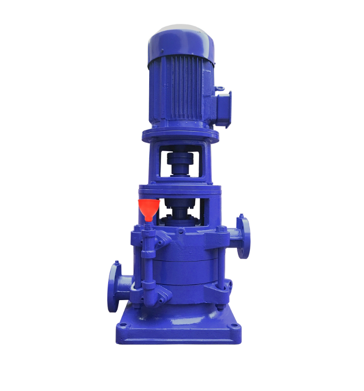
The DL Series Vertical Multistage Centrifugal Pump is a vertical, segmented multistage centrifugal pump designed for high-rise building water supply, boiler feedwater, and constant-pressure boosting systems.
It solves the problem of insufficient pressure in vertical distribution systems by delivering stable high head output through multistage hydraulic energy transfer.
It is suitable for clean water or liquids with physical and chemical properties similar to water in urban water supply, fire protection, and industrial circulation systems.
Model Designation

Applications
- High-rise building secondary water supply and pressure zoning systems
- Boiler feedwater and hot water circulation systems
- Firefighting pipeline booster systems
- Industrial cooling water circulation
- Municipal water transfer and distribution stations
Engineering Advantages
- Vertical multistage segmented hydraulic structure ensures stable high head output and smooth pressure curve.
- Coaxial inline suction and discharge configuration minimizes installation footprint and simplifies piping layout.
- Precision-machined impeller and diffuser channels improve hydraulic efficiency and reduce vibration.
- Axial thrust balancing structure reduces bearing load and enhances long-term operational stability.
System Components
The DL Series Vertical Multistage Centrifugal Pump mainly consists of:
- Pump shaft and shaft sleeve
- Multistage impellers and diffusers
- Suction and discharge casing sections
- Mechanical seal assembly
- Bearing assembly
- Motor coupling connection
Technical Specifications
Operating Conditions
- Flow rate: 6.2–300 m³/h
- Head: 23.6–225 m
- Power range: 1.5–200 kW
- Speed: 1450 rpm
- Liquid temperature: ≤ 80°C
- Working pressure: ≤ 2.5 MPa
Service Conditions
- Suitable for clean water or non-corrosive liquids without solid particles.
- Ambient temperature ≤ 40°C.
- Installation environment shall be free of explosive or aggressive gases.
- Foundation must be rigid to prevent vibration amplification.
Detailed parameter tables are provided below.
Installation & Dimensions

Performance Data
| No. | Name | Material / Model | No. | Name | Material / Model |
| 1 | Motor | Y Series (V5) 4-pole | 12 | Discharge Section | HT200 |
| 2 | Coupling | HT200 | 13 | Balance Sleeve | HT200 |
| 3 | Elastic Block | Rubber | 14 | Balance Drum | HT200 |
| 4 | Bearing Gland | HT200 | 15 | Final Stage Diffuser | HT200 |
| 5 | Bearing Nut | 45 Steel | 16 | Intermediate Section | HT200 |
| 6 | Bearing Housing | HT200 | 17 | Diffuser | HT200 |
| 7 | Bearing | 180 Series | 18 | Impeller | HT200 |
| 8 | Water-block Sleeve | 45 Steel | 19 | Suction Section | HT200 |
| 9 | Asbestos Gland | HT200 | 20 | Lower Shaft Sleeve | 45 Steel |
| 10 | Asbestos | Asbestos | 21 | Lower Bearing | Copper Alloy |
| 11 | Stuffing Box Body | HT200 | 22 | Shaft | 45 Steel / 2Cr13 |
| Note: 1. This pump type can be customized as a hot water model. 2. The asbestos packing can be replaced with a mechanical seal. 3. Please specify these requirements when ordering; pricing will be adjusted accordingly. |
|||||
Performance Parameters
| Model | Stages | Speed | Efficiency | NPSHr | Flow | Head | Power | Weight |
| r/min | % | M | m3/h | M | kw | Kg | ||
| 40DL6.2-11.2*2 | 2 | 1450 | 40 | 3.19 | 6.2 | 23.6 | 1.5 | 152 |
| 40DL6.2-11.2*3 | 3 | 1450 | 40 | 3.19 | 6.2 | 35.4 | 2.2 | 169 |
| 40DL6.2-11.2*4 | 4 | 1450 | 40 | 3.19 | 6.2 | 47.2 | 3 | 186 |
| 40DL6.2-11.2*5 | 5 | 1450 | 40 | 3.19 | 6.2 | 59 | 4 | 203 |
| 40DL6.2-11.2*6 | 6 | 1450 | 40 | 3.19 | 6.2 | 70.8 | 4 | 220 |
| 40DL6.2-11.2*7 | 7 | 1450 | 40 | 3.19 | 6.2 | 82.6 | 5.5 | 237 |
| 40DL6.2-11.2*8 | 8 | 1450 | 40 | 3.19 | 6.2 | 94.4 | 5.5 | 254 |
| 40DL6.2-11.2*9 | 9 | 1450 | 40 | 3.19 | 6.2 | 106.2 | 7.5 | 271 |
| 40DL6.2-11.2*10 | 10 | 1450 | 40 | 3.19 | 6.2 | 118 | 7.5 | / |
| 40DL6.2-11.2*11 | 11 | 1450 | 40 | 3.19 | 6.2 | 129.8 | 7.5 | / |
| 40DL6.2-11.2*12 | 12 | 1450 | 40 | 3.19 | 6.2 | 141.6 | 11 | / |
| Model | Stages | Speed | Efficiency | NPSHr | Flow | Head | Power | Weight |
| r/min | % | M | m3/h | M | kw | Kg | ||
| 50DL12.6-12.2*2 | 2 | 1450 | 54 | 2.66 | 12.6 | 24.4 | 3 | 15.3 |
| 50DL12.6-12.2*3 | 3 | 1450 | 54 | 2.66 | 12.6 | 36.6 | 3 | 18 |
| 50DL12.6-12.2*4 | 4 | 1450 | 54 | 2.66 | 12.6 | 48.8 | 4 | 23.1 |
| 50DL12.6-12.2*5 | 5 | 1450 | 54 | 2.66 | 12.6 | 61 | 5.5 | 33 |
| 50DL12.6-12.2*6 | 6 | 1450 | 54 | 2.66 | 12.6 | 73.2 | 5.5 | 24 |
| 50DL12.6-12.2*7 | 7 | 1450 | 54 | 2.66 | 12.6 | 85.4 | 7.5 | 15 |
| 50DL12.6-12.2*8 | 8 | 1450 | 54 | 2.66 | 12.6 | 97.6 | 7.5 | 18 |
| 50DL12.6-12.2*9 | 9 | 1450 | 54 | 2.66 | 12.6 | 109.8 | 11 | 22 |
| 50DL12.6-12.2*10 | 10 | 1450 | 54 | 2.66 | 12.6 | 122 | 11 | / |
| Model | Stages | Speed | Efficiency | NPSHr | Flow | Head | Power | Weight |
| r/min | % | M | m3/h | M | kw | Kg | ||
| 65DL30-16*2 | 2 | 1450 | 62 | 2.82 | 30 | 32 | 5.5 | 349 |
| 65DL30-16*3 | 3 | 1450 | 62 | 2.82 | 30 | 48 | 7.5 | 390 |
| 65DL30-16*4 | 4 | 1450 | 62 | 2.82 | 30 | 64 | 11 | 460 |
| 65DL30-16*5 | 5 | 1450 | 62 | 2.82 | 30 | 80 | 15 | 509 |
| 65DL30-16*6 | 6 | 1450 | 62 | 2.82 | 30 | 96 | 15 | 537 |
| 65DL30-16*7 | 7 | 1450 | 62 | 2.82 | 30 | 112 | 18.5 | 603 |
| 65DL30-16*8 | 8 | 1450 | 62 | 2.82 | 30 | 128 | 22 | 639 |
| 65DL30-16*9 | 9 | 1450 | 62 | 2.82 | 30 | 144 | 22 | 667 |
| 65DL30-16*10 | 10 | 1450 | 62 | 2.82 | 30 | 160 | 30 | 720 |
| Model | Stages | Speed | Efficiency | NPSHr | Flow | Head | Power | Weight |
| r/min | % | M | m3/h | M | kw | Kg | ||
| 80DL50-20*2 | 2 | 1450 | 70 | 2.5 | 50 | 40 | 11 | 461 |
| 80DL50-20*3 | 3 | 1450 | 70 | 2.5 | 50 | 60 | 15 | 522 |
| 80DL50-20*4 | 4 | 1450 | 70 | 2.5 | 50 | 80 | 22 | 608 |
| 80DL50-20*5 | 5 | 1450 | 70 | 2.5 | 50 | 100 | 30 | 728 |
| 80DL50-20*6 | 6 | 1450 | 70 | 2.5 | 50 | 120 | 30 | 768 |
| 80DL50-20*7 | 7 | 1450 | 70 | 2.5 | 50 | 140 | 37 | 822 |
| 80DL50-20*8 | 8 | 1450 | 70 | 2.5 | 50 | 160 | 45 | 898 |
| 80DL50-20*9 | 9 | 1450 | 70 | 2.5 | 50 | 180 | 45 | 938 |
| 80DL50-20*10 | 10 | 1450 | 70 | 2.5 | 50 | 200 | 55 | / |
| Model | Stages | Speed | Efficiency | NPSHr | Flow | Head | Power | Weight |
| r/min | % | M | m3/h | M | kw | Kg | ||
| 100DL72-20*2 | 2 | 1450 | 72 | 2.8 | 72 | 40 | 15 | 521 |
| 100DL72-20*3 | 3 | 1450 | 72 | 2.8 | 72 | 60 | 18.5 | 599 |
| 100DL72-20*4 | 4 | 1450 | 72 | 2.8 | 72 | 80 | 30 | 727 |
| 100DL72-20*5 | 5 | 1450 | 72 | 2.8 | 72 | 100 | 37 | 781 |
| 100DL72-20*6 | 6 | 1450 | 72 | 2.8 | 72 | 120 | 37 | 821 |
| 100DL72-20*7 | 7 | 1450 | 72 | 2.8 | 72 | 140 | 45 | 897 |
| 100DL72-20*8 | 8 | 1450 | 72 | 2.8 | 72 | 160 | 55 | 1044 |
| 100DL72-20*9 | 9 | 1450 | 72 | 2.8 | 72 | 180 | 55 | 1084 |
| 100DL72-20*10 | 10 | 1450 | 72 | 2.8 | 72 | 200 | 75 | / |
| Model | Stages | Speed | Efficiency | NPSHr | Flow | Head | Power | Weight |
| r/min | % | M | m3/h | M | kw | Kg | ||
| 100DL100-20*2 | 2 | 1450 | 72 | 3.5 | 100 | 40 | 18.5 | 554 |
| 100DL100-20*3 | 3 | 1450 | 72 | 3.5 | 100 | 60 | 30 | 687 |
| 100DL100-20*4 | 4 | 1450 | 72 | 3.5 | 100 | 80 | 37 | 746 |
| 100DL100-20*5 | 5 | 1450 | 72 | 3.5 | 100 | 100 | 45 | 827 |
| 100DL100-20*6 | 6 | 1450 | 72 | 3.5 | 100 | 120 | 55 | 979 |
| 100DL100-20*7 | 7 | 1450 | 72 | 3.5 | 100 | 140 | 75 | 1159 |
| 100DL100-20*8 | 8 | 1450 | 72 | 3.5 | 100 | 160 | 75 | 1204 |
| 100DL100-20*9 | 9 | 1450 | 72 | 3.5 | 100 | 180 | 90 | 1354 |
| 100DL100-20*10 | 10 | 1450 | 72 | 3.5 | 100 | 200 | 90 | / |
| Model | Stages | Speed | Efficiency | NPSHr | Flow | Head | Power | Weight |
| r/min | % | M | m3/h | M | kw | Kg | ||
| 150DL150-20*2 | 2 | 1450 | 80 | 2.8 | 150 | 40 | 30 | 569 |
| 150DL150-20*3 | 3 | 1450 | 80 | 2.8 | 150 | 60 | 37 | 707 |
| 150DL150-20*4 | 4 | 1450 | 80 | 2.8 | 150 | 80 | 45 | 771 |
| 150DL150-20*5 | 5 | 1450 | 80 | 2.8 | 150 | 100 | 55 | 857 |
| 150DL150-20*6 | 6 | 1450 | 80 | 2.8 | 150 | 120 | 75 | 1060 |
| 150DL150-20*7 | 7 | 1450 | 80 | 2.8 | 150 | 140 | 75 | 1245 |
| 150DL150-20*8 | 8 | 1450 | 80 | 2.8 | 150 | 160 | 90 | 1295 |
| Model | Stages | Speed | Efficiency | NPSHr | Flow | Head | Power | Weight |
| r/min | % | M | m3/h | M | kw | Kg | ||
| 150DL160-25*2 | 2 | 1450 | 76 | 3.5 | 160 | 50 | 37 | 873 |
| 150DL160-25*3 | 3 | 1450 | 76 | 3.5 | 160 | 75 | 55 | 1086 |
| 150DL160-25*4 | 4 | 1450 | 76 | 3.5 | 160 | 100 | 75 | 1291 |
| 150DL160-25*5 | 5 | 1450 | 76 | 3.5 | 160 | 125 | 90 | 1466 |
| 150DL160-25*6 | 6 | 1450 | 76 | 3.5 | 160 | 150 | 110 | 1633 |
| 150DL160-25*7 | 7 | 1450 | 76 | 3.5 | 160 | 175 | 132 | 1803 |
| 150DL160-25*8 | 8 | 1450 | 76 | 3.5 | 160 | 200 | 132 | 1873 |
| 150DL160-25*9 | 9 | 1450 | 76 | 3.5 | 160 | 225 | 160 | 2003 |
| Model | Stages | Speed | Efficiency | NPSHr | Flow | Head | Power | Weight |
| r/min | % | M | m3/h | M | kw | Kg | ||
| 200DL300-20*2 | 2 | 1450 | 79 | 5 | 300 | 40 | 55 | 983 |
| 200DL300-20*3 | 3 | 1450 | 79 | 5 | 300 | 60 | 75 | 1196 |
| 200DL300-20*4 | 4 | 1450 | 79 | 5 | 300 | 80 | 110 | 1845 |
| 200DL300-20*5 | 5 | 1450 | 79 | 5 | 300 | 100 | 132 | 1975 |
| 200DL300-20*6 | 6 | 1450 | 79 | 5 | 300 | 120 | 160 | 2120 |
| 200DL288-30*2 | 2 | 1450 | 77.9 | 3.7 | 288 | 60 | 75 | / |
| 200DL288-30*3 | 3 | 1450 | 77.9 | 3.7 | 288 | 90 | 110 | / |
| 200DL288-30*4 | 4 | 1450 | 77.9 | 3.7 | 288 | 120 | 132 | / |
| 200DL288-30*5 | 5 | 1450 | 77.9 | 3.7 | 288 | 150 | 160 | / |
| 200DL288-30*6 | 6 | 1450 | 77.9 | 3.7 | 288 | 180 | 200 | / |
Installation Diagram

Performance Data(2)
|
Model |
Stages | L | H | H1 | H2 | B | b | n-φd | Inlet Flange | Outlet Flange | ||||||
| Dj | Djn | Dj2 | n-dj | Dc | Dcn | Dc2 | n-φdc | |||||||||
| 40DL6.2-11.2 | 2 | 225 | 938 | 112 | 170 | 350 | 300 | 4-φ18 | 150 | 40 | 110 | 4-φ18 | 150 | 40 | 110 | 4-φ18 |
| 40DL6.2-11.2 | 3 | 225 | 1043 | 112 | 230 | 350 | 300 | 4-φ18 | 150 | 40 | 110 | 4-φ18 | 150 | 40 | 110 | 4-φ18 |
| 40DL6.2-11.2 | 4 | 225 | 1103 | 112 | 290 | 350 | 300 | 4-φ18 | 150 | 40 | 110 | 4-φ18 | 150 | 40 | 110 | 4-φ18 |
| 40DL6.2-11.2 | 5 | 225 | 1183 | 112 | 350 | 350 | 300 | 4-φ18 | 150 | 40 | 110 | 4-φ18 | 150 | 40 | 110 | 4-φ18 |
| 40DL6.2-11.2 | 6 | 225 | 1243 | 112 | 410 | 350 | 300 | 4-φ18 | 150 | 40 | 110 | 4-φ18 | 150 | 40 | 110 | 4-φ18 |
| 40DL6.2-11.2 | 7 | 225 | 1378 | 112 | 470 | 350 | 300 | 4-φ18 | 150 | 40 | 110 | 4-φ18 | 150 | 40 | 110 | 4-φ18 |
| 40DL6.2-11.2 | 8 | 225 | 1438 | 112 | 530 | 350 | 300 | 4-φ18 | 150 | 40 | 110 | 4-φ18 | 150 | 40 | 110 | 4-φ18 |
| 40DL6.2-11.2 | 9 | 225 | 1538 | 112 | 590 | 350 | 300 | 4-φ18 | 150 | 40 | 110 | 4-φ18 | 150 | 40 | 110 | 4-φ18 |
| 40DL6.2-11.2 | 10 | 225 | 1598 | 112 | 650 | 350 | 300 | 4-φ18 | 150 | 40 | 110 | 4-φ18 | 150 | 40 | 110 | 4-φ18 |
| 40DL6.2-11.2 | 11 | 225 | 1658 | 112 | 710 | 350 | 300 | 4-φ18 | 150 | 40 | 110 | 4-φ18 | 150 | 40 | 110 | 4-φ18 |
| 40DL6.2-11.2 | 12 | 225 | 1803 | 112 | 770 | 350 | 300 | 4-φ18 | 150 | 40 | 110 | 4-φ18 | 150 | 40 | 110 | 4-φ18 |
|
Model |
Stages | L | H | H1 | H2 | B | b | n-φd | Inlet Flange | Outlet Flange | ||||||
| Dj | Djn | Dj2 | n-dj | Dc | Dcn | Dc2 | n-φdc | |||||||||
| 50DL12.6-12.2 | 2 | 220 | 1084 | 104 | 189 | 360 | 305 | 4-φ18 | 165 | 50 | 125 | 4-φ18 | 150 | 40 | 110 | 4-φ18 |
| 50DL12.6-12.2 | 3 | 220 | 1152 | 104 | 257 | 360 | 305 | 4-φ18 | 165 | 50 | 125 | 4-φ18 | 150 | 40 | 110 | 4-φ18 |
| 50DL12.6-12.2 | 4 | 220 | 1240 | 104 | 325 | 360 | 305 | 4-φ18 | 165 | 50 | 125 | 4-φ18 | 150 | 40 | 110 | 4-φ18 |
| 50DL12.6-12.2 | 5 | 220 | 1383 | 104 | 393 | 360 | 305 | 4-φ18 | 165 | 50 | 125 | 4-φ18 | 150 | 40 | 110 | 4-φ18 |
| 50DL12.6-12.2 | 6 | 220 | 1451 | 104 | 461 | 360 | 305 | 4-φ18 | 165 | 50 | 125 | 4-φ18 | 150 | 40 | 110 | 4-φ18 |
| 50DL12.6-12.2 | 7 | 220 | 1559 | 104 | 529 | 360 | 305 | 4-φ18 | 165 | 50 | 125 | 4-φ18 | 150 | 40 | 110 | 4-φ18 |
| 50DL12.6-12.2 | 8 | 220 | 1629 | 104 | 597 | 360 | 305 | 4-φ18 | 165 | 50 | 125 | 4-φ18 | 150 | 40 | 110 | 4-φ18 |
| 50DL12.6-12.2 | 9 | 220 | 1780 | 104 | 665 | 360 | 305 | 4-φ18 | 165 | 50 | 125 | 4-φ18 | 150 | 40 | 110 | 4-φ18 |
| 50DL12.6-12.2 | 10 | 220 | 1848 | 104 | 733 | 360 | 305 | 4-φ18 | 165 | 50 | 125 | 4-φ18 | 150 | 40 | 110 | 4-φ18 |
|
Model |
Stages | L | H | H1 | H2 | B | b | n-φd | Inlet Flange | Outlet Flange | ||||||
| Dj | Djn | Dj2 | n-dj | Dc | Dcn | Dc2 | n-φdc | |||||||||
| 65DL30-16 | 2 | 260 | 1306 | 170 | 199 | 430 | 370 | 4-φ24 | 185 | 65 | 145 | 4-φ18 | 165 | 50 | 125 | 4-φ18 |
| 65DL30-16 | 3 | 260 | 1426 | 170 | 279 | 430 | 370 | 4-φ24 | 185 | 65 | 145 | 4-φ18 | 165 | 50 | 125 | 4-φ18 |
| 65DL30-16 | 4 | 260 | 1591 | 170 | 359 | 430 | 370 | 4-φ24 | 185 | 65 | 145 | 4-φ18 | 165 | 50 | 125 | 4-φ18 |
| 65DL30-16 | 5 | 260 | 1716 | 170 | 439 | 430 | 370 | 4-φ24 | 185 | 65 | 145 | 4-φ18 | 165 | 50 | 125 | 4-φ18 |
| 65DL30-16 | 6 | 260 | 1796 | 170 | 519 | 430 | 370 | 4-φ24 | 185 | 65 | 145 | 4-φ18 | 165 | 50 | 125 | 4-φ18 |
| 65DL30-16 | 7 | 260 | 1901 | 170 | 599 | 430 | 370 | 4-φ24 | 185 | 65 | 145 | 4-φ18 | 165 | 50 | 125 | 4-φ18 |
| 65DL30-16 | 8 | 260 | 2021 | 170 | 679 | 430 | 370 | 4-φ24 | 185 | 65 | 145 | 4-φ18 | 165 | 50 | 125 | 4-φ18 |
| 65DL30-16 | 9 | 260 | 2101 | 170 | 759 | 430 | 370 | 4-φ24 | 185 | 65 | 145 | 4-φ18 | 165 | 50 | 125 | 4-φ18 |
| 65DL30-16 | 10 | 260 | 2246 | 170 | 839 | 430 | 370 | 4-φ24 | 185 | 65 | 145 | 4-φ18 | 165 | 50 | 125 | 4-φ18 |
|
Model |
Stages | L | H | H1 | H2 | B | b | n-φd | Inlet Flange | Outlet Flange | ||||||
| Dj | Djn | Dj2 | n-dj | Dc | Dcn | Dc2 | n-φdc | |||||||||
| 80DL50-20 | 2 | 280 | 1515 | 120 | 277 | 450 | 400 | 4-φ24 | 200 | 80 | 160 | 8-φ18 | 185 | 65 | 145 | 4-φ18 |
| 80DL50-20 | 3 | 280 | 1649 | 120 | 366 | 450 | 400 | 4-φ24 | 200 | 80 | 160 | 8-φ18 | 185 | 65 | 145 | 4-φ18 |
| 80DL50-20 | 4 | 280 | 1865 | 120 | 455 | 450 | 400 | 4-φ24 | 200 | 80 | 160 | 8-φ18 | 185 | 65 | 145 | 4-φ18 |
| 80DL50-20 | 5 | 280 | 2030 | 120 | 544 | 450 | 400 | 4-φ24 | 200 | 80 | 160 | 8-φ18 | 185 | 65 | 145 | 4-φ18 |
| 80DL50-20 | 6 | 280 | 2120 | 120 | 633 | 450 | 400 | 4-φ24 | 200 | 80 | 160 | 8-φ18 | 185 | 65 | 145 | 4-φ18 |
| 80DL50-20 | 7 | 280 | 2270 | 120 | 722 | 450 | 400 | 4-φ24 | 200 | 80 | 160 | 8-φ18 | 185 | 65 | 145 | 4-φ18 |
| 80DL50-20 | 8 | 280 | 2385 | 120 | 811 | 450 | 400 | 4-φ24 | 200 | 80 | 160 | 8-φ18 | 185 | 65 | 145 | 4-φ18 |
| 80DL50-20 | 9 | 280 | 2475 | 120 | 900 | 450 | 400 | 4-φ24 | 200 | 80 | 160 | 8-φ18 | 185 | 65 | 145 | 4-φ18 |
| 80DL50-20 | 10 | 280 | 2665 | 120 | 989 | 450 | 400 | 4-φ24 | 200 | 80 | 160 | 8-φ18 | 185 | 65 | 145 | 4-φ18 |
|
Model |
Stages | L | H | H1 | H2 | B | b | n-φd | Inlet Flange | Outlet Flange | ||||||
| Dj | Djn | Dj2 | n-dj | Dc | Dcn | Dc2 | n-φdc | |||||||||
| 100DL72-20 | 2 | 285 | 1616 | 180 | 293 | 470 | 405 | 4-φ24 | 220 | 100 | 180 | 8-φ18 | 200 | 80 | 160 | 8-φ18 |
| 100DL72-20 | 3 | 285 | 1784 | 180 | 396 | 470 | 405 | 4-φ24 | 220 | 100 | 180 | 8-φ18 | 200 | 80 | 160 | 8-φ18 |
| 100DL72-20 | 4 | 285 | 1932 | 180 | 499 | 470 | 405 | 4-φ24 | 220 | 100 | 180 | 8-φ18 | 200 | 80 | 160 | 8-φ18 |
| 100DL72-20 | 5 | 285 | 2060 | 180 | 602 | 470 | 405 | 4-φ24 | 220 | 100 | 180 | 8-φ18 | 200 | 80 | 160 | 8-φ18 |
| 100DL72-20 | 6 | 285 | 2248 | 180 | 705 | 470 | 405 | 4-φ24 | 220 | 100 | 180 | 8-φ18 | 200 | 80 | 160 | 8-φ18 |
| 100DL72-20 | 7 | 285 | 2421 | 180 | 808 | 470 | 405 | 4-φ24 | 220 | 100 | 180 | 8-φ18 | 200 | 80 | 160 | 8-φ18 |
| 100DL72-20 | 8 | 285 | 2524 | 180 | 911 | 470 | 405 | 4-φ24 | 220 | 100 | 180 | 8-φ18 | 200 | 80 | 160 | 8-φ18 |
| 100DL72-20 | 9 | 285 | 2677 | 180 | 1014 | 470 | 405 | 4-φ24 | 220 | 100 | 180 | 8-φ18 | 200 | 80 | 160 | 8-φ18 |
| 100DL72-20 | 10 | 285 | 2780 | 180 | 1117 | 470 | 405 | 4-φ24 | 220 | 100 | 180 | 8-φ18 | 200 | 80 | 160 | 8-φ18 |
|
Model |
Stages | L | H | H1 | H2 | B | b | n-φd | Inlet Flange | Outlet Flange | ||||||
| Dj | Djn | Dj2 | n-dj | Dc | Dcn | Dc2 | n-φdc | |||||||||
| 100DL100-20 | 2 | 285 | 1493 | 180 | 293 | 470 | 405 | 4-φ24 | 220 | 100 | 180 | 8-φ18 | 200 | 80 | 160 | 8-φ18 |
| 100DL100-20 | 3 | 285 | 1655 | 180 | 396 | 470 | 405 | 4-φ24 | 220 | 100 | 180 | 8-φ18 | 200 | 80 | 160 | 8-φ18 |
| 100DL100-20 | 4 | 285 | 1777 | 180 | 499 | 470 | 405 | 4-φ24 | 220 | 100 | 180 | 8-φ18 | 200 | 80 | 160 | 8-φ18 |
| 100DL100-20 | 5 | 285 | 1807 | 180 | 602 | 470 | 405 | 4-φ24 | 220 | 100 | 180 | 8-φ18 | 200 | 80 | 160 | 8-φ18 |
| 100DL100-20 | 6 | 285 | 1984 | 180 | 705 | 470 | 405 | 4-φ24 | 220 | 100 | 180 | 8-φ18 | 200 | 80 | 160 | 8-φ18 |
| 100DL100-20 | 7 | 285 | 2111 | 180 | 808 | 470 | 405 | 4-φ24 | 220 | 100 | 180 | 8-φ18 | 200 | 80 | 160 | 8-φ18 |
| 100DL100-20 | 8 | 285 | 2213 | 180 | 911 | 470 | 405 | 4-φ24 | 220 | 100 | 180 | 8-φ18 | 200 | 80 | 160 | 8-φ18 |
| 100DL100-20 | 9 | 285 | 2415 | 180 | 1014 | 470 | 405 | 4-φ24 | 220 | 100 | 180 | 8-φ18 | 200 | 80 | 160 | 8-φ18 |
| 100DL100-20 | 10 | 285 | 2517 | 180 | 1117 | 470 | 405 | 4-φ24 | 220 | 100 | 180 | 8-φ18 | 200 | 80 | 160 | 8-φ18 |
|
Model |
Stages | L | H | H1 | H2 | B | b | n-φd | Inlet Flange | Outlet Flange | ||||||
| Dj | Djn | Dj2 | n-dj | Dc | Dcn | Dc2 | n-φdc | |||||||||
| 150DL150-20 | 2 | 310 | 1680 | 150 | 315 | 470 | 410 | 4-φ24 | 285 | 150 | 240 | 8-φ23 | 245 | 125 | 210 | 8-φ18 |
| 150DL150-20 | 3 | 310 | 1840 | 150 | 430 | 470 | 410 | 4-φ24 | 285 | 150 | 240 | 8-φ23 | 245 | 125 | 210 | 8-φ18 |
| 150DL150-20 | 4 | 310 | 2020 | 150 | 545 | 470 | 410 | 4-φ24 | 285 | 150 | 240 | 8-φ23 | 245 | 125 | 210 | 8-φ18 |
| 150DL150-20 | 5 | 310 | 2260 | 150 | 660 | 470 | 410 | 4-φ24 | 285 | 150 | 240 | 8-φ23 | 245 | 125 | 210 | 8-φ18 |
| 150DL150-20 | 6 | 310 | 2445 | 150 | 775 | 470 | 410 | 4-φ24 | 285 | 150 | 240 | 8-φ23 | 245 | 125 | 210 | 8-φ18 |
| 150DL150-20 | 7 | 310 | 2610 | 150 | 890 | 470 | 410 | 4-φ24 | 285 | 150 | 240 | 8-φ23 | 245 | 125 | 210 | 8-φ18 |
| 150DL150-20 | 8 | 310 | 2725 | 150 | 1005 | 470 | 410 | 4-φ24 | 285 | 150 | 240 | 8-φ23 | 245 | 125 | 210 | 8-φ18 |
| 150DL150-20 | 9 | 310 | 3240 | 150 | 1120 | 470 | 410 | 4-φ24 | 285 | 150 | 240 | 8-φ23 | 245 | 125 | 210 | 8-φ18 |
|
Model |
Stages | L | H | H1 | H2 | B | b | n-φd | Inlet Flange | Outlet Flange | ||||||
| Dj | Djn | Dj2 | n-dj | Dc | Dcn | Dc2 | n-φdc | |||||||||
| 150DL160-25 | 2 | 345 | 1895 | 155 | 372 | 550 | 480 | 4-φ24 | 285 | 150 | 240 | 8-φ23 | 245 | 125 | 210 | 8-φ18 |
| 150DL160-25 | 3 | 345 | 2135 | 155 | 504 | 550 | 480 | 4-φ24 | 285 | 150 | 240 | 8-φ23 | 245 | 125 | 210 | 8-φ18 |
| 150DL160-25 | 4 | 345 | 2335 | 155 | 636 | 550 | 480 | 4-φ24 | 285 | 150 | 240 | 8-φ23 | 245 | 125 | 210 | 8-φ18 |
| 150DL160-25 | 5 | 345 | 2515 | 155 | 768 | 550 | 480 | 4-φ24 | 285 | 150 | 240 | 8-φ23 | 245 | 125 | 210 | 8-φ18 |
| 150DL160-25 | 6 | 345 | 2800 | 155 | 900 | 550 | 480 | 4-φ24 | 285 | 150 | 240 | 8-φ23 | 245 | 125 | 210 | 8-φ18 |
| 150DL160-25 | 7 | 345 | 2975 | 155 | 1032 | 550 | 480 | 4-φ24 | 285 | 150 | 240 | 8-φ23 | 245 | 125 | 210 | 8-φ18 |
| 150DL160-25 | 8 | 345 | 3110 | 155 | 1164 | 550 | 480 | 4-φ24 | 285 | 150 | 240 | 8-φ23 | 245 | 125 | 210 | 8-φ18 |
| 150DL160-25 | 9 | 345 | 3240 | 155 | 1260 | 550 | 480 | 4-φ24 | 285 | 150 | 240 | 8-φ23 | 245 | 125 | 210 | 8-φ18 |
|
Model |
Stages | L | H | H1 | H2 | B | b | n-φd | Inlet Flange | Outlet Flange | ||||||
| Dj | Djn | Dj2 | n-dj | Dc | Dcn | Dc2 | n-φdc | |||||||||
| 200DL300-20 | 2 | 380 | 2010 | 182 | 600 | 600 | 550 | 4-φ24 | 340 | 200 | 295 | 12-φ23 | 285 | 150 | 240 | 8-φ23 |
| 200DL300-20 | 3 | 380 | 2320 | 182 | 760 | 600 | 550 | 4-φ24 | 340 | 200 | 295 | 12-φ23 | 285 | 150 | 240 | 8-φ23 |
| 200DL300-20 | 4 | 380 | 2660 | 182 | 905 | 600 | 550 | 4-φ24 | 340 | 200 | 295 | 12-φ23 | 285 | 150 | 240 | 8-φ23 |
| 200DL300-20 | 5 | 380 | 2860 | 182 | 1050 | 600 | 550 | 4-φ24 | 340 | 200 | 295 | 12-φ23 | 285 | 150 | 240 | 8-φ23 |
| 200DL300-20 | 6 | 380 | 3010 | 182 | 1200 | 600 | 550 | 4-φ24 | 340 | 200 | 295 | 12-φ23 | 285 | 150 | 240 | 8-φ23 |
| 200DL288-30 | 2 | 380 | 2185 | 182 | 600 | 600 | 550 | 4-φ24 | 340 | 200 | 295 | 12-φ23 | 285 | 150 | 240 | 8-φ23 |
| 200DL288-30 | 3 | 380 | 2355 | 182 | 760 | 600 | 550 | 4-φ24 | 340 | 200 | 295 | 12-φ23 | 285 | 150 | 240 | 8-φ23 |
| 200DL288-30 | 4 | 380 | 2795 | 182 | 905 | 600 | 550 | 4-φ24 | 340 | 200 | 295 | 12-φ23 | 285 | 150 | 240 | 8-φ23 |
| 200DL288-30 | 5 | 380 | 2945 | 182 | 1050 | 600 | 550 | 4-φ24 | 340 | 200 | 295 | 12-φ23 | 285 | 150 | 240 | 8-φ23 |
| 200DL288-30 | 6 | 380 | 3095 | 182 | 1200 | 600 | 550 | 4-φ24 | 340 | 200 | 295 | 12-φ23 | 285 | 150 | 240 | 8-φ23 |
Installation Dimensions
|
|
|
||||||||||||||||||||||||||||||||||||||||||||||||||||||


Installation Diagram(2)
|
|
|||||||||||||||||||||||||||||||||||||


|
||||||||||||||||||||||||||||||||||||||||||||||||||||||||||||||||||||||||||||||||||||||||||||||||||||||||||||||||||||||
How to Select a Pump Model
- Determine required flow rate and total dynamic head including pipeline loss.
- Ensure duty point falls within high-efficiency region of performance curve.
- Verify medium temperature and compatibility with seal materials.
- For vertical high-rise systems, confirm zoning pressure limits.
- Consider VFD control if system demand varies.
Engineering Notes
- Not suitable for liquids containing abrasive solids or fibrous materials.
- Proper axial alignment must be verified after installation.
- Long pipeline systems should include non-return valves.
- Continuous operation systems should include standby units.
Compliance & Quality Assurance
- Factory hydraulic performance testing
- Hydrostatic pressure test of casing
- Rotor dynamic balance inspection
- Bearing clearance and vibration verification
- Material traceability documentation
- Optional third-party inspection
Safety Notice
- Do not operate under dry-running condition
- Ensure suction priming before startup
- Disconnect power before maintenance
- Do not exceed rated discharge pressure
OEM & Customization
This pump series supports engineered configuration and duty-based matching.
Available options include:
- Motor voltage & frequency
- Mechanical seal type and configuration
- Wetted parts material selection
- Surface coating and corrosion protection
Configuration is determined based on duty point and project specifications.
FAQs
- Q: Can the pump operate under VFD control?
A: Yes, operation under VFD is permitted within rated hydraulic limits. - Q: What is the allowable working pressure?
A: The maximum allowable working pressure is 2.5 MPa. - Q: What seal options are available?
A: Mechanical seal is standard; special configurations available upon request. - Q: What type of medium is permitted?
A: Clean water or non-corrosive liquids without solid particles. - Q: What rotational speeds are available?
A: Standard speeds are 1450 rpm and 2900 rpm. - Q: How is axial thrust controlled?
A: Axial thrust is reduced through balancing hydraulic structure.