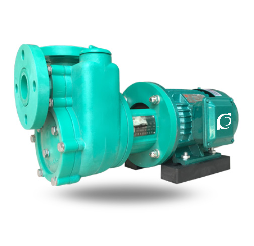
Product Overview
FPZ Self-Priming Corrosion-Resistant Pump (CFR/PP Series) is a horizontal self-priming centrifugal pump constructed from corrosion-resistant engineering plastics for transferring acidic and alkaline chemical media in industrial systems.
It solves corrosion failure of metallic pumps, suction limitations in tank-top installations, and leakage risks in aggressive chemical handling processes.
It is applied in acid/alkali transfer stations, electroplating circulation systems, chemical tank unloading operations, and corrosive wastewater lifting systems.
Model Designation

Applications
Typical Operating Scenarios
• Acid or alkali unloading from ground storage tanks without foot valve
• Electroplating solution circulation in surface treatment production lines
• Chemical dosing systems with intermittent start-stop operation
• Scrubber circulation in exhaust gas neutralization systems
• Corrosive wastewater transfer pits requiring suction lift
Engineering Advantages
Structural Design Logic & Engineering Result
• PP / FRPP / PVDF molded casing structure ensures resistance against strong acids and alkalis, extending operational life in aggressive chemical environments.
• Integrated self-priming chamber with internal recirculation design enables automatic suction without auxiliary vacuum equipment.
• Non-metallic wetted components eliminate electrochemical corrosion and contamination risk.
• Back pull-out configuration allows maintenance without removing pipeline connections.
• Optimized hydraulic impeller reduces cavitation under intermittent duty conditions.
System Components
FPZ Self-Priming Corrosion-Resistant Pump (CFR/PP Series) :
• Pump casing (PP / FRPP / PVDF optional)
• Self-priming chamber
• Closed impeller
• Pump shaft
• Mechanical seal assembly
• Motor
• Base frame
Technical Specifications
Service Conditions
• Suitable for corrosive liquids without large solid particles
• Media temperature within material resistance range
Operating Conditions
- Flow Rate: 1.5 – 60 m³/h
- Head: 10 – 52 m
- Power Range: 0.75 – 15 kW
- Speed: 2900 rpm
- Liquid Temperature: ≤ 80°C
- Working Pressure: ≤ 0.6 MPa
Detailed parameter tables are provided below.
Specifications & Installation
Performance Curves

Performance Parameters
| Model | Diameter (mm) | Flow (m3/h) | Head (m) | Motor Power (kw) | Speed (r/min) | Self-Priming Height (m) | |
| Inlet | Outlet | ||||||
| 25FPZ-10 (Self-Priming) | 25 | 25 | 2.5 | 10 | 0.75 | 2900 | 3 |
| 32FPZ-11 (Self-Priming) | 32 | 25 | 3.5 | 11 | 0.75 | 2900 | 3 |
| 40FPZ-18 (Self-Priming) | 40 | 32 | 11 | 18 | 1.5 | 2900 | 4 |
| 50FPZ-20 (Self-Priming) | 50 | 40 | 13 | 20 | 2.2 | 2900 | 4 |
| 65FPZ-25 (Self-Priming) | 65 | 50 | 20 | 25 | 4 | 2900 | 4 |
| 80FPZ-32 (Self-Priming) | 80 | 65 | 50 | 32 | 7.5 | 2900 | 4 |
Data & Installation Diagram
| 1 | Inlet Flange | 9 | Impeller Shaft |  |
| 2 | Front Pump Cover | 10 | Bracket | |
| 3 | Outlet Flange | 11 | Oil Cap | |
| 4 | Liquid Injection | 12 | Tie Rod Bolt | |
| 5 | Pump Shell | 13 | Coupling | |
| 6 | Impeller | 14 | Base Plate | |
| 7 | Rear Pump Cover | 15 | Motor | |
| 8 | Mechanical Seal |
Performance Parameters(2)
| Model | L | L1 | L2 | L3 | L4 | H | H1 | H2 | B | B2 | B1 | D1 | D2 | 4-d |
| 25FPZ-10 | 460 | 290 | 100 | 110 | 60 | 260 | 190 | 50 | 150 | 110 | 110 | 100 | 85 | 12 |
| 32FPZ-11 | 460 | 290 | 100 | 110 | 60 | 260 | 190 | 50 | 150 | 110 | 110 | 100 | 85 | 18 |
| 40FPZ-18Direct-Coupled | 560 | 345 | 100 | 110 | 70 | 285 | 200 | 50 | 190 | 140 | 140 | 110 | 100 | 18 |
| 40FPZ-18Coupled | 780 | 300 | 345 | 105 | 70 | 300 | 220 | 60 | 290 | 250 | 210 | 110 | 100 | 18 |
| 50FPZ-20Direct-Coupled | 570 | 345 | 125 | 110 | 70 | 285 | 200 | 50 | 190 | 140 | 140 | 125 | 110 | 18 |
| 50FPZ-20Coupled | 790 | 290 | 345 | 105 | 70 | 300 | 220 | 60 | 290 | 250 | 210 | 125 | 110 | 18 |
| 65FPZ-28Direct-Coupled | 670 | 400 | 140 | 145 | 80 | 340 | 250 | 50 | 240 | 190 | 190 | 145 | 125 | 18 |
| 65FPZ-28Coupled | 950 | 395 | 365 | 145 | 80 | 400 | 310 | 95 | 335 | 275 | 250 | 145 | 125 | 18 |
| 80FPZ-30 | 1030 | 422 | 385 | 175 | 110 | 420 | 325 | 100 | 380 | 330 | 255 | 150 | 145 | 18 |
Performance Parameters(3)
| Model |
Flow Rate
(m3/h) |
Head
(m) |
Diameter
(mm) |
Motor Power
(Kw) |
Self-Priming Lift”
(m) |
Speed(r/min) | |
| 25FZB-20 | 1.5 | 23 | 25 | 25 | 1.5 | 3 | 2900 |
| 3.6 | 20 | ||||||
| 4.5 | 17 | ||||||
| 40FZB-20 | 5 | 22 | 40 | 40 | 3 | 3 | 2900 |
| 8 | 20 | ||||||
| 10 | 17 | ||||||
| 40FZB-30 | 5 | 33 | 40 | 40 | 3 | 3 | 2900 |
| 8 | 30 | ||||||
| 10 | 25 | ||||||
| 50FZB-20 | 8 | 25 | 50 | 50 | 3 | 3 | 2900 |
| 12 | 20 | ||||||
| 15 | 17 | ||||||
| 50FZB-30 | 8 | 33 | 50 | 50 | 3 | 3 | 2900 |
| 12 | 30 | ||||||
| 15 | 25 | ||||||
| 50FZB-45L | 8 | 48.5 | 50 | 32 | 7.5 | 3 | 2900 |
| 12 | 45 | ||||||
| 15 | 40 | ||||||
| 65FZB-20L | 20 | 23 | 65 | 50 | 4 | 3.5 | 2900 |
| 25 | 20 | ||||||
| 30 | 17 | ||||||
| 65FZB-30L | 20 | 33 | 65 | 50 | 7.5 | 3.5 | 2900 |
| 25 | 30 | ||||||
| 30 | 25 | ||||||
| 65FZB-40L | 20 | 42 | 65 | 50 | 11 | 3.5 | 2900 |
| 25 | 40 | ||||||
| 30 | 30 | ||||||
| 65FZB-45L | 20 | 47 | 65 | 50 | 11 | 3.5 | 2900 |
| 25 | 45 | ||||||
| 30 | 40 | ||||||
| 65FZB-50L | 20 | 52 | 65 | 50 | 15 | 3.5 | 2900 |
| 25 | 50 | ||||||
| 30 | 45 | ||||||
| 80FZB-20L | 30 | 23 | 80 | 65 | 5.5 | 4 | 2900 |
| 40 | 20 | ||||||
| 50 | 15 | ||||||
| 80FZB-30L | 40 | 33 | 80 | 65 | 11 | 4 | 2900 |
| 50 | 30 | ||||||
| 60 | 25 | ||||||
| 80FZB-45L | 40 | 48.5 | 80 | 65 | 15 | 4 | 2900 |
| 50 | 45 | ||||||
| 60 | 40 | ||||||
Corrosion Resistance of Materials
| Medium | Concentration | CFR-PP | Medium | Concentration | |||||||||
| 25℃ | 65℃ | 90℃ | 20℃ | 60℃ | 80℃ | ||||||||
| H2SO4 | 98% | √ | √ | ○ | H2SO4 | <30% | √ | X | |||||
| 70% | √ | √ | 30~70% | ○ | X | ||||||||
| 1~50% | √ | √ | √ | >75% | X | X | |||||||
| HNO3 | Concentration | √ | √ | ○ | HNO3 | 10% | √ | ○ | |||||
| 20% | √ | √ | √ | 20% | √ | ||||||||
| 10% | √ | √ | √ | 25~35% | ○ | ||||||||
| >50% | X | X | |||||||||||
| HC1 | 0~30% | √ | ○ | X | HC1 | >30% | √ | X | |||||
| Hydrofluoric Acid | √ | X | X | Hydrofluoric Acid | >10% | √ | X | ||||||
| 40~48% | √ | X | |||||||||||
|
1~50% | √ | √ | √ |
|
>20% | √ | ○ | |||||
| Phosphoric Acid | Various concentrations | √ | √ | √ | Phosphoric Acid | >30% | X | X | |||||
| Sodium Hydroxide | √ | √ | √ | Sodium Hydroxide | √ | √ | √ | ||||||
| Sodium Chloride | √ | √ | √ | Sodium Chloride | √ | √ | X | ||||||
| Sodium Chloride | √ | √ | |||||||||||
|
√ | √ | √ |
|
√ | √ | |||||||
| Bleach | √ | √ | √ | Bleach | ○ | ○ | X | ||||||
How to Select a Pump Model
• Confirm chemical compatibility between media and pump material (PP / FRPP / PVDF).
• Determine required suction lift and piping layout to verify self-priming capacity.
• Define duty point (flow & head) based on system resistance calculation.
• Evaluate temperature and concentration of chemical solution.
• Consider intermittent or continuous operation frequency.
Engineering Notes
• Self-priming performance depends on correct initial filling of pump casing.
• Maximum suction height is affected by altitude and medium vapor pressure.
• Mechanical seal selection should match chemical compatibility.
• Pump should be installed on rigid foundation to minimize vibration.
Compliance & Quality Assurance
• Factory hydraulic performance test before shipment
• Material traceability for wetted plastic components
• Mechanical seal pressure integrity verification
• Optional third-party inspection upon request
Safety Notice
• Do not operate under dry-running condition
• Ensure pump casing is filled before startup
• Disconnect power before maintenance
• Do not exceed allowable working pressure
OEM & Custom
This pump series supports engineered configuration and duty-based matching. Technical adjustments can be made according to system requirements and installation conditions.
Available options include:
• Motor voltage & frequency
• Mechanical seal type and configuration
• Wetted parts material selection
• Surface coating and corrosion protection
Configuration is determined based on duty point and project specifications.
FAQs
Q: Can the pump operate under VFD control?
A: Yes, operation under variable frequency control is permissible within rated power range.
Q: What is the allowable working pressure?
A: Maximum working pressure is 0.6 MPa.
Q: What materials are available for wetted parts?
A: PP, FRPP, and PVDF are available depending on chemical compatibility.
Q: What is the maximum suction height?
A: Typically up to 5–6 meters under standard conditions.
Q: Is the pump suitable for high-concentration acids?
A: Suitability depends on chemical compatibility verification with selected material.
Q: What sealing options are available?
A: Single mechanical seal is standard; material combinations vary by medium.