Product Overview
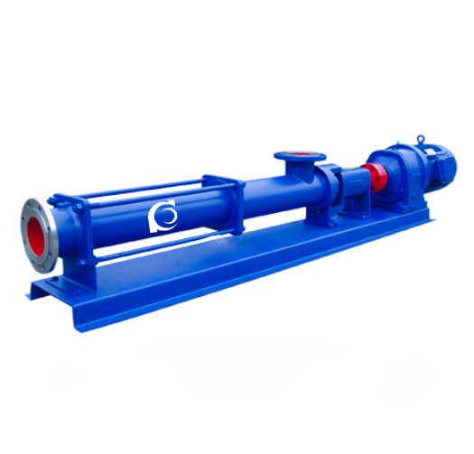
The G Series Single Screw Pump is a positive displacement rotary pump based on the eccentric rotor principle. This series, also known internationally as a single pump or eccentric rotor pump, is designed for pumping slurries containing solids, fibers, and suspended materials. It is characterized by low wear, no packing, and clog-free operation, providing smooth, continuous pumping and excellent adaptability to a wide range of media.
Model Designation

Key Features
-
Powerful Solid Handling Capability: The single-screw design is capable of handling slurries containing solids and fibers with minimal wear.
-
Low Pulsation and Smooth Delivery: Ensures continuous flow with very low pressure pulsation, maintaining stable operation.
-
High Self-Priming Capability: Offers excellent self-priming ability, making it suitable for various types of media.
-
Compact and Simple Design: Fewer components, reducing maintenance requirements and simplifying on-site repair.
Engineering Overview
The G Series has been developed into a complete product system. Each stage has a rated discharge pressure of 0.6 MPa, with a standard operating pressure range of 0.6–1.2 MPa, and the maximum pressure for special applications can reach up to 3 MPa. By increasing the number of stages, discharge pressure can be flexibly increased to meet diverse system demands.
Typical Applications
The G Series Single Screw Pump is widely used in:
-
High Viscosity Fluid Transport: Particularly suitable for pumping high-viscosity liquids and media containing solids or fibers.
-
Precise Flow Control: Ideal for applications requiring precise and stable flow control, such as in chemical processing, food industries, and mining.
-
Industrial Wastewater and Sludge Transport: Efficiently handles slurries containing solid particles, ensuring stable flow and pressure.
System Configuration
Pump Components
The G Series Single Screw Pump’s key components include the eccentric screw (rotor) and fixed stator (liner). The unique geometry of these components creates multiple independent sealing chambers inside the pump, enabling continuous medium delivery and stable pressure generation.
Components and Supply
The G Series pumps offer flexible component configurations, including different impeller types and materials, such as cast iron or stainless steel, to meet varying operational conditions and provide reliable performance.
Technical Service
The G Series pumps provide comprehensive technical support, including installation, commissioning, regular maintenance, and troubleshooting services, ensuring long-term stable operation of the equipment.
Operating Conditions
-
Rated Discharge Pressure per Stage: 0.6 MPa (approximately 60 meters head under clean water conditions).
-
Typical Self-Priming Height: 6 meters.
-
Medium Temperature: Standard type ≤80°C; special applications up to 150°C.
-
Pressure Increment by Stages: Each additional stage adds 0.6 MPa of discharge pressure.
Service Conditions
Regular inspection of the pump’s sealing system, eccentric screw, and stator components is recommended to ensure efficient and safe operation.
Protection Features
The G Series pumps are equipped with multiple protection features, including overcurrent protection, temperature monitoring, and liquid level protection systems, ensuring the pump can stop operating in abnormal conditions to prevent damage to the equipment.
Selection Standards
When selecting the pump model, consider factors such as the temperature of the media, pH value, solid particle size, and the required flow and head of the pump, ensuring the selection of the most suitable configuration.
Specifications & Installation
Outline Drawing

Performance Data
|
1
|
Discharge port
|
2
|
Tie rod
|
3
|
Stator
|
4
|
Screw shaft
|
5
|
Universal joint assembly
|
6
|
Suction port
|
|
7
|
Connecting shaft
|
8
|
Packing housing
|
9
|
Packing gland
|
10
|
Bearing housing
|
11
|
Bearing cover
|
12
|
Motor
|
|
13
|
Coupling
|
14
|
Shaft sleeve
|
15
|
Bearing
|
16
|
Drive shaft
|
17
|
Base
|
Performance Parameters
|
Model
|
Speed
r/min |
Flow
m3/h |
Pressure
MPa |
Motor
kW |
Head
m |
Inlet
mm |
Outlet
mm |
Allowable particle diameter
mm |
Allowable maintenance length
mm |
|
G20-1
|
960
|
0.8
|
0.6
|
0.75
|
60
|
25
|
25
|
1.5
|
25
|
|
G20-2
|
960
|
0.8
|
1.2
|
1.5
|
60
|
25
|
25
|
1.5
|
25
|
|
G25-1
|
960
|
2
|
0.6
|
1.5
|
60
|
32
|
25
|
2
|
30
|
|
G25-2
|
960
|
2
|
1.2
|
2.2
|
120
|
32
|
25
|
2
|
30
|
|
G30-1
|
960
|
5
|
0.6
|
2.2
|
60
|
50
|
40
|
2.5
|
35
|
|
G30-2
|
960
|
5
|
1.2
|
3.0
|
120
|
50
|
40
|
2.5
|
35
|
|
G35-1
|
960
|
8
|
0.6
|
3.0
|
60
|
65
|
50
|
3
|
40
|
|
G35-2
|
960
|
8
|
1.2
|
4.0
|
120
|
65
|
50
|
3
|
40
|
|
G40-1
|
960
|
12
|
0.6
|
4.0
|
60
|
80
|
65
|
3.8
|
45
|
|
G40-2
|
960
|
12
|
1.2
|
5.5
|
120
|
80
|
65
|
3.8
|
45
|
|
G50-1
|
960
|
20
|
0.6
|
5.5
|
60
|
100
|
80
|
5
|
50
|
|
G50-2
|
960
|
20
|
1.2
|
7.5
|
120
|
100
|
80
|
5
|
50
|
|
G60-1
|
960
|
30
|
0.6
|
11
|
60
|
125
|
100
|
6
|
60
|
|
G60-2
|
960
|
30
|
1.2
|
15
|
120
|
125
|
100
|
6
|
60
|
|
G70-1
|
960
|
45
|
0.6
|
15
|
60
|
150
|
125
|
8
|
70
|
|
G70-2
|
720
|
45
|
1.2
|
18.5
|
120
|
150
|
125
|
8
|
70
|
|
G85-1
|
720
|
65
|
0.6
|
15
|
60
|
150
|
150
|
10
|
80
|
|
G105-1
|
500
|
100
|
0.6
|
22
|
60
|
200
|
200
|
15
|
110
|
|
G135-1
|
400
|
150
|
0.6
|
37
|
60
|
250
|
250
|
20
|
150
|
Operating Manual
Please Note
-
The test data in the performance table is based on clean water at 20°C with a viscosity of 1mm²/s.
-
When the pump conveys high-viscosity media or media containing particles, the pump speed should be adjusted according to the properties of the medium.
-
When conveying media with different levels of abrasiveness, the pump speed should also be adjusted accordingly.
Important Notes
-
Always confirm the direction of rotation before starting; reverse rotation is strictly prohibited.
-
It is strictly prohibited to run the pump dry without medium to prevent damage to the stator.
-
For newly installed pumps or pumps that have been shut down for several days, do not start directly. First, inject an appropriate amount of lubricating oil into the pump body, then rotate the pump several revolutions with a pipe wrench before starting.
-
After conveying high-viscosity, particle-laden, or corrosive media, flush the pump with water or a suitable cleaning agent to prevent blockage and avoid difficulty in the next startup.
-
In winter, drain any residual liquid in the pump to prevent freezing and cracking.
-
During operation, lubricating oil should be added periodically to the bearing housing. If leakage is found at the shaft end, handle it promptly or replace the oil seal.
-
If any abnormal conditions occur during operation, stop the pump immediately, check the cause, and eliminate the fault before restarting.