Product Overview
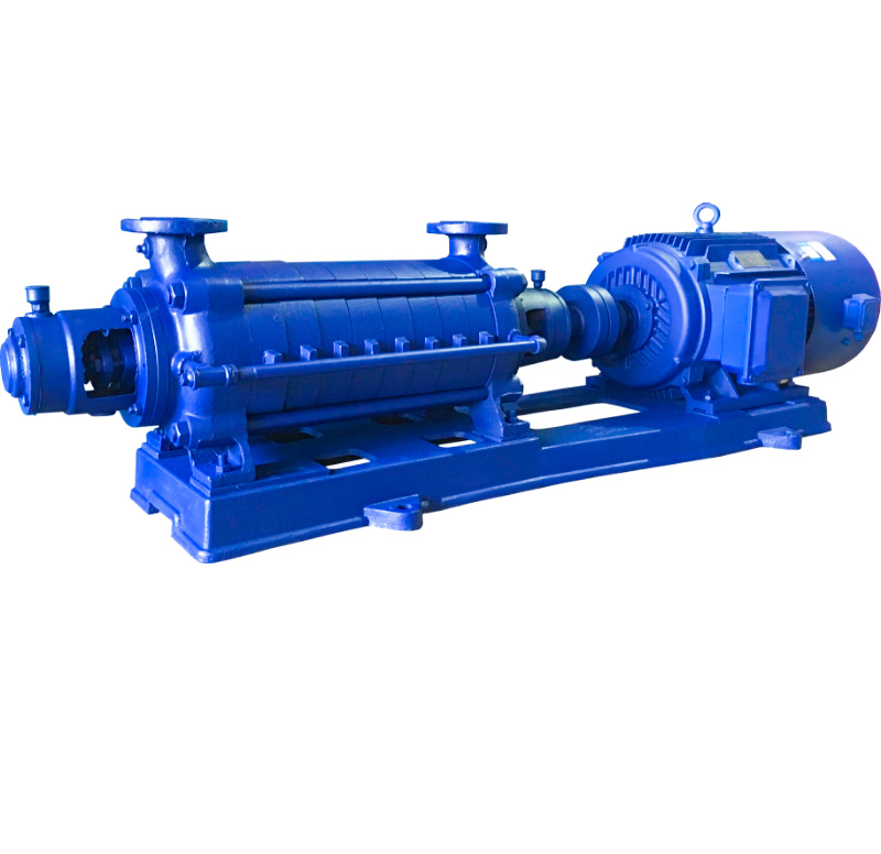
The GC Horizontal Boiler Feed Multistage Centrifugal Pump is a new type of horizontal, single-suction, multistage centrifugal pump designed primarily for boiler feed applications. It is suitable for transporting clean water and other non-corrosive liquids with similar physical and chemical properties to water at temperatures up to 110°C.
This pump series is widely used in industrial and mining enterprises, public facilities, and municipal household water supply systems, particularly for boiler feed systems.
Model Designation

Key Features
-
Multi-stage sectional design, allows for adjusting the head by adding or removing stages to meet different operational requirements.
-
Precise alignment of the impeller and diffuser ensures stable flow, head, and efficiency.
-
Balanced impellers during the manufacturing process minimize vibration.
-
Axial thrust is balanced by a balancing disc and balancing ring assembly for stable operation.
-
Cast iron sealing rings reduce internal leakage, improving efficiency.
-
Durable shaft and bearing configuration ensure long service life.
-
Simple structure, with clear wear parts for easy maintenance.
Engineering Summary
The GC pump adopts a multi-stage sectional structure. For models from 1-1/2GC to 4GC, the inlet and discharge nozzles are arranged vertically upward on the suction sleeve and discharge casing, respectively. The pump head can be adjusted by adding or removing stages to meet varying operational conditions.
Pump performance is highly dependent on assembly precision, especially the alignment between each impeller outlet and the corresponding diffuser inlet. Precise concentric alignment is crucial, as even slight misalignment can reduce flow, head, and efficiency. Reassembly requires careful inspection and adjustment.
Typical Applications
-
Boiler feed systems
-
Pressure vessel water supply
-
Hot water circulation systems
-
High-rise building water supply
-
Agricultural irrigation
-
Firefighting pressure enhancement
-
Hydraulic washing systems
-
Food processing, brewing, pharmaceutical, and chemical industries
-
Aquaculture, environmental protection, chemical processing systems
-
Mechanical support systems for water supply and drainage
System Configuration
The GC system primarily consists of the following core components:
-
Pump shaft and shaft sleeve
-
Suction sleeve
-
Driver
-
Discharge diffuser
-
Middle casing
-
Discharge casing
-
Sealing rings
-
Balancing ring and balancing disc assembly
-
End cover
-
Bearings: Single-row deep groove ball bearings, lubricated with calcium-based grease
-
Packing seal assembly: Includes stuffing box, gland, lantern ring, and packing
Components and Supply
GC system components include:
-
Pump body, bearing assembly
-
Mechanical seal and shaft support system
-
Electric motor and drive system
-
Pipe fittings and installation accessories
Technical Service
The GC pump system provides comprehensive technical support and services, including installation and commissioning, operational monitoring, and maintenance recommendations. We provide detailed operation manuals, installation instructions, and remote technical support.
Operating Conditions
-
Pumped medium: Clean water or non-corrosive liquids with similar properties to water.
-
Maximum liquid temperature: ≤110°C
-
Ambient temperature: ≤40°C
-
Bearing lubricants: Calcium-based grease
-
Suitable for continuous operation in boiler feed and pressurization systems.
Service Conditions
-
Fire hydrant system: Water gun flow rate of 2.5L/S, 5L/S, with jet lengths of 7m, 10m, and 13m.
-
Automatic sprinkler system: Flow rate of 1.0L/S per nozzle, with a nozzle pressure of 0.1MPa.
-
The environment temperature of the device: 5°C to 40°C.
Protection Functions
The GC system is equipped with various protection functions, including overload protection, overpressure protection, and mechanical fault detection, ensuring safe and stable operation of the pump system under various extreme conditions.
Selection Criteria
The selection of the GC pump should be based on the specific application scenario, required flow rate, and head requirements. Consideration should also be given to installation space, ease of maintenance, and long-term system stability.
Installation & Dimensions
Outline Drawing

Performance Data
| 1 | Shaft Sleeve Nut | 2 | Bearing Cover | 3 | Bearing | 4 | Front Bearing Housing | 5 | Shaft Sleeve (A) | 6 | Packing Gland | 7 | Lantern Ring |
| 8 | Wear Ring | 9 | Suction Casing | 10 | Impeller | 11 | Middle Casing | 12 | Return Pipe | 13 | Discharge Casing | 14 | Balance Ring |
| 15 | Balance Disc | 16 | Tail Cover | 17 | Shaft Sleeve (B) | 18 | Shaft | 19 | Round Nut | 20 | Tension Bolt |
Performance Parameters
| Model | Stages | Flow Rate Q | Total Head H | Speed n | Power N (kW) | Efficiency η | NPSH | Impeller Diameter | Weight | ||
| m3/h | L/S | m | r/min | Shaft Power | Motor Power (kW) | % | m | mm | Kg | ||
| 11/2GC-5 | 2 | 6 | 1.66 | 46 | 2950 | 2 | 3 | 38 | 3.7 | 136 | 135 |
| 11/2GC-5 | 3 | 6 | 1.66 | 69 | 2920 | 3 | 4 | 38 | 3.7 | 136 | 147 |
| 11/2GC-5 | 4 | 6 | 1.66 | 92 | 2920 | 4 | 5.5 | 38 | 3.7 | 136 | 174 |
| 11/2GC-5 | 5 | 6 | 1.66 | 115 | 2920 | 5 | 7.5 | 38 | 3.7 | 136 | 204 |
| 11/2GC-5 | 6 | 6 | 1.66 | 138 | 2920 | 6 | 7.5 | 38 | 3.7 | 136 | 212 |
| 11/2GC-5 | 7 | 6 | 1.66 | 161 | 2920 | 7 | 7.5 | 38 | 3.7 | 136 | 220 |
| 11/2GC-5 | 8 | 6 | 1.66 | 184 | 2920 | 8 | 11 | 38 | 3.7 | 136 | 271 |
| 11/2GC-5 | 9 | 6 | 1.66 | 207 | 2920 | 9 | 15 | 38 | 3.7 | 136 | 292 |
| Model | Stages | Flow Rate Q | Total Head H | Speed n | Power N (kW) | Efficiency η | NPSH | Impeller Diameter | Weight | ||
| m3/h | L/S | m | r/min | Shaft Power | Motor Power (kW) | % | m | mm | Kg | ||
| 2GC-5 | 2 | 10 | 2.8 | 64 | 2950 | 4.4 | 7.5 | 39.6 | 4.7 | 166 | 258 |
| 2GC-5 | 3 | 10 | 2.8 | 96 | 2950 | 6.6 | 11 | 39.6 | 4.7 | 166 | 309 |
| 2GC-5 | 4 | 10 | 2.8 | 128 | 2950 | 8.8 | 15 | 39.6 | 4.7 | 166 | 389 |
| 2GC-5 | 5 | 10 | 2.8 | 160 | 2950 | 11.0 | 15 | 39.6 | 4.7 | 166 | 414 |
| 2GC-5 | 6 | 10 | 2.8 | 192 | 2950 | 13.2 | 18.5 | 39.6 | 4.7 | 166 | 512 |
| 2GC-5 | 7 | 10 | 2.8 | 224 | 2950 | 15.4 | 22.0 | 39.6 | 4.7 | 166 | 531 |
| 2GC-5 | 8 | 10 | 2.8 | 256 | 2950 | 17.6 | 30.0 | 39.6 | 4.7 | 166 | 589 |
| 2GC-5 | 9 | 10 | 2.8 | 288 | 2950 | 19.8 | 30.0 | 39.6 | 4.7 | 166 | 609 |
| Model | Stages | Flow Rate Q | Total Head H | Speed n | Power N (kW) | Efficiency η | NPSH | Impeller Diameter | Weight | ||
| m3/h | L/S | m | r/min | Shaft Power | Motor Power (kW) | % | m | mm | Kg | ||
| 21/2GC-3.5 | 7 |
10
15 20 |
2.8
4.2 5.6 |
336
315 280 |
2950 |
26
28.6 32.5 |
37 |
35
45 47 |
3.3
3.8 4 |
198 | 967 |
| 21/2GC-3.5 | 8 |
10
15 20 |
2.8
4.2 5.6 |
384
360 320 |
2950 |
30
32.8 37 |
45 |
35
45 47 |
3.3
3.8 4 |
198 | 1065 |
| 21/2GC-3.5 | 9 |
10
15 20 |
2.8
4.2 5.6 |
432
405 360 |
2950 |
33.7
37 42 |
55 |
35
45 47 |
3.3
3.8 4 |
198 | 1097 |
| 21/2GC-3.5 | 10 |
10
15 20 |
2.8
4.2 5.6 |
480
450 400 |
2950 |
37.5
41 46.5 |
55 |
35
45 47 |
3.3
3.8 4 |
198 | 1179 |
| 21/2GC-3.5 | 11 |
10
15 20 |
2.8
4.2 5.6 |
528
495 440 |
2950 |
41.5
45 51 |
75 |
35
45 47 |
3.3
3.8 4 |
198 | 1252 |
| 21/2GC-3.5 | 12 |
10
15 20 |
2.8
4.2 5.6 |
576
540 480 |
2950 |
45
49 56 |
75 |
35
45 47 |
3.3
3.8 4 |
198 | 1324 |
| Model | Stages | Flow Rate Q | Total Head H | Speed n | Power N (kW) | Efficiency η | NPSH | Impeller Diameter | Weight | ||
| m3/h | L/S | m | r/min | Shaft Power | Motor Power (kW) | % | m | mm | Kg | ||
| 21/2GC-6 | 2 |
15
20 |
4.2
5.6 |
62
54 |
2950 |
5.8
6.2 |
7.5 |
43.7
47.4 |
5
5.3 |
168 | 258 |
| 21/2GC-6 | 3 |
15
20 |
4.2
5.6 |
93
81 |
2950 |
8.7
9.3 |
15 |
43.7
47.4 |
5
5.3 |
168 | 309 |
| 21/2GC-6 | 4 |
15
20 |
4.2
5.6 |
124
108 |
2950 |
11.6
12.4 |
18.5 |
43.7
47.4 |
5
5.3 |
168 | 389 |
| 21/2GC-6 | 5 |
15
20 |
4.2
5.6 |
155
135 |
2950 |
14.5
15.5 |
22.0 |
43.7
47.4 |
5
5.3 |
168 | 494 |
| 21/2GC-6 | 6 |
15
20 |
4.2
5.6 |
186
162 |
2950 |
17.4
18.6 |
22.0 |
43.7
47.4 |
5
5.3 |
168 | 512 |
| 21/2GC-6 | 7 |
15
20 |
4.2
5.6 |
217
189 |
2950 |
20.2
21.7 |
30.0 |
43.7
47.4 |
5
5.3 |
168 | 563 |
| 21/2GC-6 | 8 |
15
20 |
4.2
5.6 |
248
216 |
2950 |
23.2
24.8 |
30.0 |
43.7
47.4 |
5
5.3 |
168 | 589 |
| 21/2GC-6 | 9 |
15
20 |
4.2
5.6 |
279
243 |
2950 |
26.1
27.9 |
37.0 |
43.7
47.4 |
5
5.3 |
168 | 785 |
| Model | Stages | Flow Rate Q | Total Head H | Speed n | Power N (kW) | Efficiency η | NPSH | Impeller Diameter | Weight | ||
| m3/h | L/S | m | r/min | Shaft Power | Motor Power (kW) | % | m | mm | Kg | ||
| 4GC-8 | 2 |
30
45 55 |
8.3
12.5 15.3 |
86
82 79 |
2950 |
13.8
16.8 18.1 |
22 |
51
60 62.5 |
4.6
5 5.6 |
192 | 503 |
| 4GC-8 | 3 |
30
45 55 |
8.3
12.5 15.3 |
129
123 114 |
2950 |
20.7
25.2 27.2 |
30 |
51
60 62.5 |
4.6
5 5.6 |
192 | 612 |
| 4GC-8 | 4 |
30
45 55 |
8.3
12.5 15.3 |
172
164 152 |
2950 |
27.6
33.6 35.2 |
45 |
51
60 62.5 |
4.6
5 5.6 |
192 | 835 |
| 4GC-8 | 5 |
30
45 55 |
8.3
12.5 15.3 |
215
205 190 |
2950 |
34.5
42 45.3 |
55 |
51
60 62.5 |
4.6
5 5.6 |
192 | 950 |
| 4GC-8 | 6 |
30
45 55 |
8.3
12.5 15.3 |
258
246 228 |
2950 |
41.4
50.4 54.4 |
55 |
51
60 62.5 |
4.6
5 5.6 |
192 | 1085 |
| 4GC-8 | 7 |
30
45 55 |
8.3
12.5 15.3 |
301
287 266 |
2950 |
48.3
58.8 63.4 |
75 |
51
60 62.5 |
4.6
5 5.6 |
192 | 1087 |
| 4GC-8 | 8 |
30
45 55 |
8.3
12.5 15.3 |
344
328 304 |
2950 |
55
67 73 |
75 |
51
60 62.5 |
4.6
5 5.6 |
192 | |
| 4GC-8 | 9 |
30
45 55 |
8.3
12.5 15.3 |
387
369 342 |
2950 |
62
75.5 82 |
90 |
51
60 62.5 |
4.6
5 5.6 |
192 | |
| 4GC-8 | 10 |
30
45 55 |
8.3
12.5 15.3 |
430
410 380 |
2950 |
69
84 91 |
100 |
51
60 62.5 |
4.6
5 5.6 |
192 | |
Installation Diagram

Performance Data(2)
| Model | Number of Stages | A | B | C | E | H | I | J | K | L | M | N | O | P | Q | F | n-φd |
| 11/2GC-5 | 2 | 963 | 750 | 510 | 128 | 248 | 122.5 | 355 | 350 | 205 | 365 | 105 | 180 | 315 | 315 | 154 | 4-φ20 |
| 11/2GC-5 | 3 | 1033 | 805 | 535 | 125 | 248 | 172.5 | 355 | 358 | 205 | 405 | 115 | 190 | 355 | 355 | 154 | 4-φ20 |
| 11/2GC-5 | 4 | 1158 | 1010 | 715 | 135 | 248 | 222.5 | 360 | 393 | 205 | 415 | 135 | 210 | 365 | 365 | 47 | 4-φ20 |
| 11/2GC-5 | 5 | 1208 | 1010 | 715 | 135 | 248 | 272.5 | 360 | 393 | 205 | 415 | 135 | 210 | 365 | 365 | 97 | 4-φ20 |
| 11/2GC-5 | 6 | 1258 | 1010 | 715 | 135 | 248 | 322.5 | 360 | 393 | 205 | 415 | 135 | 210 | 365 | 365 | 147 | 4-φ20 |
| 11/2GC-5 | 7 |
1308
1433 |
1060
1180 |
715
760 |
135
170 |
248 | 372.5 | 360 |
393
495 |
205 |
415
470 |
135
163 |
210
255 |
365 |
365
240 |
147
100 |
4-φ20 |
| 11/2GC-5 | 8 | 1484 | 1280 | 785 | 170 | 248 | 422.5 | 395 | 470 | 205 | 470 | 165 | 255 | 365 | 420 | 95 | 4-φ20 |
| 11/2GC-5 | 9 | 1533 | 1280 | 785 | 170 | 248 | 472.5 | 395 | 470 | 205 | 470 | 165 | 255 | 365 | 420 | 145 | 4-φ20 |
| Model | Number of Stages | A | B | C | E | H | I | J | K | L | M | N | O | P | Q | F | n-φd |
| 2GC-5 | 2 | 1227 | 915 | 650 | 135 | 325 | 160 | 480 | 443 | 255 | 490 | 135 | 210 | 430 | 430 | 211 | 4-φ24 |
| 2GC-5 | 3 | 1412 | 1160 | 790 | 165 | 325 | 220 | 485 | 490 | 255 | 480 | 165 | 255 | 430 | 430 | 141 | 4-φ24 |
| 2GC-5 | 4 | 1412 | 1160 | 790 | 165 | 325 | 280 | 485 | 490 | 255 | 480 | 165 | 255 | 430 | 430 | 201 | 4-φ24 |
| 2GC-5 | 5 | 1532 | 1220 | 820 | 165 | 325 | 340 | 485 | 490 | 255 | 480 | 165 | 255 | 430 | 430 | 201 | 4-φ24 |
| 2GC-5 | 6 | 1637 | 1320 | 860 | 185 | 325 | 400 | 485 | 490 | 255 | 480 | 165 | 255 | 430 | 430 | 203 | 4-φ24 |
| 2GC-5 | 7 | 1722 | 1380 | 900 | 200 | 325 | 460 | 480 | 510 | 255 | 515 | 180 | 285 | 455 | 455 | 209 | 4-φ24 |
| 2GC-5 | 8 | 1887 | 1575 | 1000 | 240 | 325 | 520 | 525 | 580 | 255 | 585 | 200 | 310 | 440 | 525 | 150 | 4-φ24 |
| 2GC-5 | 9 | 1947 | 1575 | 1000 | 240 | 325 | 580 | 525 | 580 | 255 | 585 | 200 | 310 | 440 | 525 | 210 | 4-φ24 |
| Model | Number of Stages | A | B | C | E | H | I | J | K | L | M | N | O | P | Q | F | n-φd |
| 21/2GC-3.5 | 7 | 1937 | 1590 | 1030 | 225 | 385 | 470 | 608 | 598 | 295 | 600 | 200 | 310 | 540 | 540 | 195 | 4-φ24 |
| 21/2GC-3.5 | 8 | 1937 | 1675 | 1085 | 225 | 385 | 530 | 618 | 638 | 295 | 600 | 225 | 345 | 540 | 540 | 194 | 4-φ24 |
| 21/2GC-3.5 | 9 | 2212 | 1835 | 1170 | 265 | 385 | 590 | 643 | 683 | 295 | 600 | 250 | 385 | 540 | 610 | 192 | 4-φ24 |
| 21/2GC-3.5 | 10 | 2272 | 1895 | 1200 | 265 | 385 | 650 | 643 | 683 | 295 | 600 | 250 | 385 | 540 | 610 | 192 | 4-φ24 |
| 21/2GC-3.5 | 11 | 2402 | 2115 | 1280 | 320 | 385 | 710 | 675 | 750 | 295 | 715 | 280 | 410 | 530 | 655 | 131 | 4-φ24 |
| 21/2GC-3.5 | 12 | 2462 | 2115 | 1280 | 320 | 385 | 770 | 675 | 750 | 295 | 715 | 280 | 410 | 530 | 655 | 191 | 4-φ24 |
| 型号 | Number of Stages | A | B | C | E | H | I | J | K | L | M | N | O | P | Q | F | n-φd |
| 21/2GC-6 | 2 | 1227 | 915 | 650 | 135 | 325 | 160 | 480 | 443 | 255 | 490 | 135 | 210 | 430 | 430 | 211 | 4-φ24 |
| 21/2GC-6 | 3 | 1412 | 1160 | 790 | 165 | 325 | 220 | 485 | 490 | 255 | 480 | 165 | 255 | 430 | 430 | 141 | 4-φ24 |
| 21/2GC-6 | 4 | 1412 | 1160 | 790 | 165 | 325 | 280 | 485 | 490 | 255 | 480 | 165 | 255 | 430 | 430 | 201 | 4-φ24 |
| 21/2GC-6 | 5 | 1577 | 1320 | 860 | 185 | 325 | 340 | 485 | 490 | 255 | 480 | 165 | 255 | 430 | 430 | 143 | 4-φ24 |
| 21/2GC-6 | 6 | 1662 | 1380 | 900 | 200 | 325 | 400 | 480 | 510 | 255 | 515 | 180 | 285 | 455 | 455 | 149 | 4-φ24 |
| 21/2GC-6 | 7 | 1827 | 1575 | 1000 | 240 | 325 | 460 | 525 | 580 | 255 | 585 | 200 | 310 | 440 | 525 | 90 | 4-φ24 |
| 21/2GC-6 | 8 | 1887 | 1575 | 1000 | 240 | 325 | 520 | 525 | 580 | 255 | 585 | 200 | 310 | 440 | 525 | 150 | 4-φ24 |
| 21/2GC-6 | 9 | 1947 | 1575 | 1000 | 240 | 325 | 525 | 525 | 580 | 255 | 585 | 200 | 310 | 440 | 525 | 210 | 4-φ24 |
| Model | Number of Stages | A | B | C | E | H | I | J | K | L | M | N | O | P | Q | F | n-φd |
| 4GC-8 | 2 | 1552 | 1230 | 845 | 190 | 385 | 190 | 610 | 575 | 295 | 600 | 180 | 285 | 540 | 480 | 185 | 4-φ24 |
| 4GC-8 | 3 | 1732 | 1385 | 925 | 225 | 385 | 265 | 610 | 600 | 295 | 600 | 200 | 310 | 540 | 540 | 185 | 4-φ24 |
| 4GC-8 | 4 | 1847 | 1485 | 980 | 235 | 385 | 340 | 620 | 640 | 295 | 600 | 225 | 345 | 540 | 540 | 184 | 4-φ24 |
| 4GC-8 | 5 | 2037 | 1735 | 1105 | 265 | 385 | 415 | 645 | 685 | 295 | 665 | 250 | 385 | 540 | 605 | 117.5 | 4-φ24 |
| 4GC-8 | 6 | 2112 | 1735 | 1105 | 265 | 385 | 490 | 645 | 685 | 295 | 665 | 250 | 385 | 540 | 605 | 192.5 | 4-φ24 |
| 4GC-8 | 7 | 2257 | 1955 | 1215 | 300 | 385 | 565 | 675 | 750 | 295 | 720 | 280 | 410 | 540 | 660 | 116.5 | 4-φ24 |
| 4GC-8 | 8 | 2332 | 1955 | 1215 | 300 | 385 | 640 | 675 | 750 | 295 | 720 | 280 | 410 | 540 | 660 | 191.5 | 4-φ24 |
| 4GC-8 | 9 | 2457 | 2080 | 1295 | 325 | 385 | 715 | 675 | 750 | 295 | 720 | 280 | 410 | 540 | 660 | 191.5 | 4-φ24 |
Outline Drawing(2)

Performance Data(2)
| Dimension | Suction Flange | |||
| Model | Dg | Do | D | n–do |
| 11/2GC-5 | 40 | 115 | 145 | 4-φ18 |
| 2GC-5 | 50 | 125 | 160 | 4-φ18 |
| 21/2GC-6 | 65 | 145 | 180 | 8-φ18 |
Pump Installation & Performance
Pump Head H Calculation:

Pump Head and Installation Calculations:
In the formula:
-
P1: Suction pressure (MPa)
-
P2: Discharge pressure (MPa)
-
Z1: Vertical distance from the suction pressure gauge to the pump shaft center (m)
-
Z2: Vertical distance from the discharge pressure gauge to the pump shaft center (m)
-
V1: Flow velocity at the suction point (m/s)
-
V2: Flow velocity at the discharge measuring point (m/s)
-
ρ: Liquid density (kg/m³)
-
g: Gravitational acceleration (9.8 m/s²)
Pump Installation Height (Mercury Alloy Calculation):
(Installation height refers to the vertical distance from the pump shaft centerline to the liquid level)
High point ≤ P0 – [NPSH] – P’ – △h – 0.5(m)
In the formula:
-
P0: Atmospheric pressure (or absolute pressure at the liquid surface) (water column unit)
-
[NPSH]: Net Positive Suction Head required by the pump (m)
-
P’: Vapor pressure of the pumped liquid (m water column)
-
△h: Hydraulic head loss (m)
Note:
When the pump shaft center is above the liquid level, the pump is positive (indicating suction mode).
When the value is negative, the pump is in submerged suction mode (indicating the pump is submerged in liquid).
The pump’s flow rate (Q), head (H), and shaft power (N) are related to the actual pump speed.
Calculation formula:

Operating Manual
Assembly and Disassembly
(I) Pump Disassembly Instructions
-
Follow the shutdown sequence to stop the pump.
-
Drain the liquid from the pump casing (including cooling water). If the bearings use oil lubrication, drain the oil as well.
-
Remove any auxiliary pipelines obstructing disassembly, such as balancing pipes, sealing water pipes, and electrical wires.
-
During disassembly, strictly protect the processing precision of all components. When removing the tie rod, use blocks to support the middle of the band tube to prevent the connecting joint from loosening or sinking, which could potentially bend the pump shaft.
(II) Pump Disassembly Sequence
-
Remove the bolts on the bearing end cover of the discharge side and the connecting bolts between the discharge casing, tail cover, and bearing casing. Remove the bearing end cover and bearing casing components.
-
Remove the circular nut on the shaft, then take out the inner bearing ring, bearing gland, and retaining ring. Disassemble the packing box assembly (including packing gland, lantern ring, and packing).
-
Remove the O-ring, shaft sleeve, balance disk, and key from the shaft. Then, remove the discharge sleeve, upper diffuser half, balance ring, and sleeve.
-
Remove the final impeller and key, then take out the middle casing and diffuser. Continue removing impellers, mid casings, and diffusers in stages until the first stage impeller is removed.
-
Remove the pump joint, then remove the connecting nuts between the suction casing and bearing casing and disassemble the bearing casing on the suction side.
-
Pull the shaft from the suction tube surface, remove the shaft nut, and take out the inner bearing ring, O-ring, shaft sleeve, etc.
-
For pumps with sleeve bearings, the operation method is similar, but the procedure for removing bearing components may differ slightly.
(III) Pump Assembly
Assembly is usually carried out in reverse order of disassembly. The quality of assembly directly affects the pump’s performance, service life, and reliability.
Key Points:
-
Protect the processing precision and surface smoothness of the components. Avoid scratches or dents. Molybdenum disulfide used for sealing must remain clean. All bolts and screws should be tightened to the correct torque.
-
Ensure proper axial dimensioning of each component to align the impeller outlet channel with the corresponding diffuser inlet channel. Misalignment can affect pump performance. The pump dimensions should not be altered at will.
-
After assembly and before installing packing, manually rotate the rotor to check if it rotates smoothly, and confirm that axial end movement is within tolerance.
-
After inspection, install the packing and ensure the lantern ring is correctly aligned in the packing chamber.
Preparation Work
(I) Startup Preparation
-
Rotate the pump rotor by hand before startup to ensure it rotates freely.
-
Confirm that the motor’s rotation direction matches the pump’s rotation direction.
-
Open the inlet valve, close the discharge valve, and the pressure gauge bracket to ensure the pump is fully primed, or use a vacuum system to evacuate air from the suction pipe and pump casing.
-
Check the tightness of the bolts connecting the pump and motor, and ensure the surrounding area is safe. The pump must be fully prepared for operation.
-
Power on the motor. After the pump reaches a stable speed, open the pressure gauge hole and gradually open the discharge valve until the pressure gauge indicates the desired discharge pressure (which corresponds to the required pump head).
(II) Operation
The pump series employs a balancing mechanism to offset axial thrust. Balanced water flows back into the suction pipe through a balancing pipe or via an external short pipe. The balancing water pipe must never be clogged.
2) During startup and operation, monitor instrument readings, bearing temperatures, packing leakage, pump vibration, and noise. Immediately address any abnormal conditions.
3) A rise in bearing temperature reflects assembly quality. The temperature increase in bearings should not exceed 35°C above ambient temperature. The maximum bearing temperature should not exceed 75°C.
4) The pump rotor will have a certain amount of axial float during operation. The axial shift must remain within the allowable range. Maintain proper clearance between the motor and pump coupling.
5) Periodically check components such as the impeller, wear rings, lantern rings, shaft sleeves, and balance discs for wear. Replace parts when significant wear occurs.
(III) Shutdown
-
Before stopping, close the discharge valve gradually, and then cut off the power supply to the motor. After the pump has completely stopped, close the inlet valve.
-
Drain the liquid from the pump. For long-term shutdown, disassemble, clean, lubricate, and properly store the pump.
OEM & Custom
We provide OEM/ODM manufacturing with customizable materials (cast iron, stainless steel, alloy steel), voltages (220V/415V/460V), and control systems. Options include explosion-proof motors, extended shafts, and flange customization (DIN/ANSI/JIS). Each pump is hydraulically tested to meet ISO9001 and CE standards for global markets.
FAQs
- Q: What is the main application of GC multistage pumps?
A: Mainly used for boiler feed, pressure boosting, and clean water supply in industrial and municipal systems. - Q: What is the maximum temperature the pump can handle?
A: Up to 110°C for clean or slightly hot water applications. - Q: What materials are available?
A: Standard cast iron; optional stainless steel or alloy for specific industrial fluids. - Q: What is the maximum head and flow range?
A: Head up to 400 meters; flow rate 6–55 m³/h depending on model and stage number. - Q: What kind of seal is used?
A: Standard packing seal; mechanical seals available for optional configurations. - Q: How should the pump be maintained?
A: Regular lubrication, seal inspection, and yearly performance checks are recommended. - Q: Which industries use GC pumps?
A: Power plants, manufacturing, chemical processing, HVAC, and water supply projects globally.