Product Overview
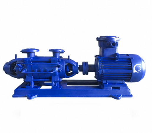
The GC Series Horizontal Multistage Boiler Feed Pump is a single-suction centrifugal pump designed for continuous, reliable operation in boiler feed and make-up water systems.
It handles high-load and fluctuating water quality conditions, providing efficient energy transfer for optimal stability and low energy consumption.
Ideal for industrial, municipal, and high-rise building water systems, ensuring reliable performance in boiler systems, pressure vessel water supply, and hot water circulation.
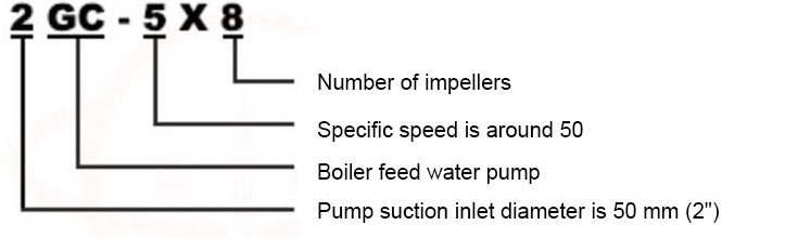
Model Designation
Applications
The GC series pump is widely used in:
- Industrial & municipal boiler feedwater systems
- High-rise building water supply & firefighting boosting
- Food, pharmaceutical & hygiene-critical processing
- Aquaculture, environmental protection & special applications
Engineering Advantages
- The GC Series Horizontal Boiler Feed Pump features a sectional multistage structure, allowing flexible adjustment of the pump head by adding or removing stages.
- The pump’s modular design ensures ease of inspection and maintenance, making it ideal for continuous operations in industrial and municipal systems.
- The precise coaxial alignment between impeller outlets and diffuser inlets enhances operational efficiency, reducing wear and tear during use.
System Components
The GC series pump consists of the following key components:
- Shaft and shaft sleeves
- Impellers and diffusers
- Seal rings
- Intermediate and discharge sections
- Balancing disc and rear cover
- High-quality carbon steel shaft and cast iron components
Technical Specifications
- Flow rate: 6 – 55 m³/h
- Head: 46 – 576 m
- Power range: 3 – 100 kW
- Speed: 2920 – 2950 rpm
- Liquid temperature: ≤ 110°C
- Working pressure: ≤ 4.0 MPa
Service Conditions
- The installation site should be free from explosive gases or aggressive media.
- Recommended ambient temperature ≤ 40°C, relative humidity ≤ 95%.
- The foundation must be stable to prevent vibration and ensure long-term performance.
nstallation & Dimensions
Outline Drawing

Performance Data
| 1 | Shaft Sleeve Nut | 2 | Bearing Cover | 3 | Bearing | 4 | Front Bearing Housing | 5 | Front Shaft Sleeve | 6 | Packing Gland | 7 | Packing Ring |
| 8 | Seal Ring | 9 | Suction Section | 10 | Impeller | 11 | Middle Section | 12 | Return Pipe | 13 | Discharge Section | 14 | Balance Ring |
| 15 | Balance Plate | 16 | Tail Cover | 17 | Rear Shaft Sleeve | 18 | Shaft | 19 | Round Nut | 20 | Tightening Bolt |
Performance Parameters
| Model | Stages | Flow Rate | Total Head | Rotational Speed | Power (kW) | Efficiency (η) | NPSHr | Impeller Diameter | Weight | ||
| m3/h | L/S | m | r/min | Light-load Power | Motor Power | % | m | mm | Kg | ||
| 11/2GC-5 | 2 | 6 | 1.66 | 46 | 2950 | 2 | 3 | 38 | 3.7 | 136 | 135 |
| 11/2GC-5 | 3 | 6 | 1.66 | 69 | 2920 | 3 | 4 | 38 | 3.7 | 136 | 147 |
| 11/2GC-5 | 4 | 6 | 1.66 | 92 | 2920 | 4 | 5.5 | 38 | 3.7 | 136 | 174 |
| 11/2GC-5 | 5 | 6 | 1.66 | 115 | 2920 | 5 | 7.5 | 38 | 3.7 | 136 | 204 |
| 11/2GC-5 | 6 | 6 | 1.66 | 138 | 2920 | 6 | 7.5 | 38 | 3.7 | 136 | 212 |
| 11/2GC-5 | 7 | 6 | 1.66 | 161 | 2920 | 7 | 7.5 | 38 | 3.7 | 136 | 220 |
| 11/2GC-5 | 8 | 6 | 1.66 | 184 | 2920 | 8 | 11 | 38 | 3.7 | 136 | 271 |
| 11/2GC-5 | 9 | 6 | 1.66 | 207 | 2920 | 9 | 15 | 38 | 3.7 | 136 | 292 |
| Model | Stages | Flow Rate | Total Head | Rotational Speed | Power (kW) | Efficiency (η) | NPSHr | Impeller Diameter | Weight | ||
| m3/h | L/S | m | r/min | Light-load Power | Motor Power | % | m | mm | Kg | ||
| 2GC-5 | 2 | 10 | 2.8 | 64 | 2950 | 4.4 | 7.5 | 39.6 | 4.7 | 166 | 258 |
| 2GC-5 | 3 | 10 | 2.8 | 96 | 2950 | 6.6 | 11 | 39.6 | 4.7 | 166 | 309 |
| 2GC-5 | 4 | 10 | 2.8 | 128 | 2950 | 8.8 | 15 | 39.6 | 4.7 | 166 | 389 |
| 2GC-5 | 5 | 10 | 2.8 | 160 | 2950 | 11.0 | 15 | 39.6 | 4.7 | 166 | 414 |
| 2GC-5 | 6 | 10 | 2.8 | 192 | 2950 | 13.2 | 18.5 | 39.6 | 4.7 | 166 | 512 |
| 2GC-5 | 7 | 10 | 2.8 | 224 | 2950 | 15.4 | 22.0 | 39.6 | 4.7 | 166 | 531 |
| 2GC-5 | 8 | 10 | 2.8 | 256 | 2950 | 17.6 | 30.0 | 39.6 | 4.7 | 166 | 589 |
| 2GC-5 | 9 | 10 | 2.8 | 288 | 2950 | 19.8 | 30.0 | 39.6 | 4.7 | 166 | 609 |
| Model | Stages | Flow Rate | Total Head | Rotational Speed | Power (kW) | Efficiency (η) | NPSHr | Impeller Diameter | Weight | ||
| m3/h | L/S | m | r/min | Light-load Power | Motor Power | % | m | mm | Kg | ||
| 21/2GC-3.5 | 7 |
10
15 20 |
2.8
4.2 5.6 |
336
315 280 |
2950 |
26
28.6 32.5 |
37 |
35
45 47 |
3.3
3.8 4 |
198 | 967 |
| 21/2GC-3.5 | 8 |
10
15 20 |
2.8
4.2 5.6 |
384
360 320 |
2950 |
30
32.8 37 |
45 |
35
45 47 |
3.3
3.8 4 |
198 | 1065 |
| 21/2GC-3.5 | 9 |
10
15 20 |
2.8
4.2 5.6 |
432
405 360 |
2950 |
33.7
37 42 |
55 |
35
45 47 |
3.3
3.8 4 |
198 | 1097 |
| 21/2GC-3.5 | 10 |
10
15 20 |
2.8
4.2 5.6 |
480
450 400 |
2950 |
37.5
41 46.5 |
55 |
35
45 47 |
3.3
3.8 4 |
198 | 1179 |
| 21/2GC-3.5 | 11 |
10
15 20 |
2.8
4.2 5.6 |
528
495 440 |
2950 |
41.5
45 51 |
75 |
35
45 47 |
3.3
3.8 4 |
198 | 1252 |
| 21/2GC-3.5 | 12 |
10
15 20 |
2.8
4.2 5.6 |
576
540 480 |
2950 |
45
49 56 |
75 |
35
45 47 |
3.3
3.8 4 |
198 | 1324 |
| Model | Stages | Flow Rate | Total Head | Rotational Speed | Power (kW) | Efficiency (η) | NPSHr | Impeller Diameter | Weight | ||
| m3/h | L/S | m | r/min | Light-load Power | Motor Power | % | m | mm | Kg | ||
| 21/2GC-6 | 2 |
15
20 |
4.2
5.6 |
62
54 |
2950 |
5.8
6.2 |
7.5 |
43.7
47.4 |
5
5.3 |
168 | 258 |
| 21/2GC-6 | 3 |
15
20 |
4.2
5.6 |
93
81 |
2950 |
8.7
9.3 |
15 |
43.7
47.4 |
5
5.3 |
168 | 309 |
| 21/2GC-6 | 4 |
15
20 |
4.2
5.6 |
124
108 |
2950 |
11.6
12.4 |
18.5 |
43.7
47.4 |
5
5.3 |
168 | 389 |
| 21/2GC-6 | 5 |
15
20 |
4.2
5.6 |
155
135 |
2950 |
14.5
15.5 |
22.0 |
43.7
47.4 |
5
5.3 |
168 | 494 |
| 21/2GC-6 | 6 |
15
20 |
4.2
5.6 |
186
162 |
2950 |
17.4
18.6 |
22.0 |
43.7
47.4 |
5
5.3 |
168 | 512 |
| 21/2GC-6 | 7 |
15
20 |
4.2
5.6 |
217
189 |
2950 |
20.2
21.7 |
30.0 |
43.7
47.4 |
5
5.3 |
168 | 563 |
| 21/2GC-6 | 8 |
15
20 |
4.2
5.6 |
248
216 |
2950 |
23.2
24.8 |
30.0 |
43.7
47.4 |
5
5.3 |
168 | 589 |
| 21/2GC-6 | 9 |
15
20 |
4.2
5.6 |
279
243 |
2950 |
26.1
27.9 |
37.0 |
43.7
47.4 |
5
5.3 |
168 | 785 |
| Model | Stages | Flow Rate | Total Head | Rotational Speed | Power (kW) | Efficiency (η) | NPSHr | Impeller Diameter | Weight | ||
| m3/h | L/S | m | r/min | Light-load Power | Motor Power | % | m | mm | Kg | ||
| 4GC-8 | 2 |
30
45 55 |
8.3
12.5 15.3 |
86
82 79 |
2950 |
13.8
16.8 18.1 |
22 |
51
60 62.5 |
4.6
5 5.6 |
192 | 503 |
| 4GC-8 | 3 |
30
45 55 |
8.3
12.5 15.3 |
129
123 114 |
2950 |
20.7
25.2 27.2 |
30 |
51
60 62.5 |
4.6
5 5.6 |
192 | 612 |
| 4GC-8 | 4 |
30
45 55 |
8.3
12.5 15.3 |
172
164 152 |
2950 |
27.6
33.6 35.2 |
45 |
51
60 62.5 |
4.6
5 5.6 |
192 | 835 |
| 4GC-8 | 5 |
30
45 55 |
8.3
12.5 15.3 |
215
205 190 |
2950 |
34.5
42 45.3 |
55 |
51
60 62.5 |
4.6
5 5.6 |
192 | 950 |
| 4GC-8 | 6 |
30
45 55 |
8.3
12.5 15.3 |
258
246 228 |
2950 |
41.4
50.4 54.4 |
55 |
51
60 62.5 |
4.6
5 5.6 |
192 | 1085 |
| 4GC-8 | 7 |
30
45 55 |
8.3
12.5 15.3 |
301
287 266 |
2950 |
48.3
58.8 63.4 |
75 |
51
60 62.5 |
4.6
5 5.6 |
192 | 1087 |
| 4GC-8 | 8 |
30
45 55 |
8.3
12.5 15.3 |
344
328 304 |
2950 |
55
67 73 |
75 |
51
60 62.5 |
4.6
5 5.6 |
192 | |
| 4GC-8 | 9 |
30
45 55 |
8.3
12.5 15.3 |
387
369 342 |
2950 |
62
75.5 82 |
90 |
51
60 62.5 |
4.6
5 5.6 |
192 | |
| 4GC-8 | 10 |
30
45 55 |
8.3
12.5 15.3 |
430
410 380 |
2950 |
69
84 91 |
100 |
51
60 62.5 |
4.6
5 5.6 |
192 | |
Installation Dimensions

Performance Data(2)
| Model | Number of Stages | A | B | C | E | H | I | J | K | L | M | N | O | P | Q | F | n-φd |
| 11/2GC-5 | 2 | 963 | 750 | 510 | 128 | 248 | 122.5 | 355 | 350 | 205 | 365 | 105 | 180 | 315 | 315 | 154 | 4-φ20 |
| 11/2GC-5 | 3 | 1033 | 805 | 535 | 125 | 248 | 172.5 | 355 | 358 | 205 | 405 | 115 | 190 | 355 | 355 | 154 | 4-φ20 |
| 11/2GC-5 | 4 | 1158 | 1010 | 715 | 135 | 248 | 222.5 | 360 | 393 | 205 | 415 | 135 | 210 | 365 | 365 | 47 | 4-φ20 |
| 11/2GC-5 | 5 | 1208 | 1010 | 715 | 135 | 248 | 272.5 | 360 | 393 | 205 | 415 | 135 | 210 | 365 | 365 | 97 | 4-φ20 |
| 11/2GC-5 | 6 | 1258 | 1010 | 715 | 135 | 248 | 322.5 | 360 | 393 | 205 | 415 | 135 | 210 | 365 | 365 | 147 | 4-φ20 |
| 11/2GC-5 | 7 |
1308
1433 |
1060
1180 |
715
760 |
135
170 |
248 | 372.5 | 360 |
393
495 |
205 |
415
470 |
135
163 |
210
255 |
365 |
365
240 |
147
100 |
4-φ20 |
| 11/2GC-5 | 8 | 1484 | 1280 | 785 | 170 | 248 | 422.5 | 395 | 470 | 205 | 470 | 165 | 255 | 365 | 420 | 95 | 4-φ20 |
| 11/2GC-5 | 9 | 1533 | 1280 | 785 | 170 | 248 | 472.5 | 395 | 470 | 205 | 470 | 165 | 255 | 365 | 420 | 145 | 4-φ20 |
| Model | Number of Stages | A | B | C | E | H | I | J | K | L | M | N | O | P | Q | F | n-φd |
| 2GC-5 | 2 | 1227 | 915 | 650 | 135 | 325 | 160 | 480 | 443 | 255 | 490 | 135 | 210 | 430 | 430 | 211 | 4-φ24 |
| 2GC-5 | 3 | 1412 | 1160 | 790 | 165 | 325 | 220 | 485 | 490 | 255 | 480 | 165 | 255 | 430 | 430 | 141 | 4-φ24 |
| 2GC-5 | 4 | 1412 | 1160 | 790 | 165 | 325 | 280 | 485 | 490 | 255 | 480 | 165 | 255 | 430 | 430 | 201 | 4-φ24 |
| 2GC-5 | 5 | 1532 | 1220 | 820 | 165 | 325 | 340 | 485 | 490 | 255 | 480 | 165 | 255 | 430 | 430 | 201 | 4-φ24 |
| 2GC-5 | 6 | 1637 | 1320 | 860 | 185 | 325 | 400 | 485 | 490 | 255 | 480 | 165 | 255 | 430 | 430 | 203 | 4-φ24 |
| 2GC-5 | 7 | 1722 | 1380 | 900 | 200 | 325 | 460 | 480 | 510 | 255 | 515 | 180 | 285 | 455 | 455 | 209 | 4-φ24 |
| 2GC-5 | 8 | 1887 | 1575 | 1000 | 240 | 325 | 520 | 525 | 580 | 255 | 585 | 200 | 310 | 440 | 525 | 150 | 4-φ24 |
| 2GC-5 | 9 | 1947 | 1575 | 1000 | 240 | 325 | 580 | 525 | 580 | 255 | 585 | 200 | 310 | 440 | 525 | 210 | 4-φ24 |
| Model | Number of Stages | A | B | C | E | H | I | J | K | L | M | N | O | P | Q | F | n-φd |
| 21/2GC-3.5 | 7 | 1937 | 1590 | 1030 | 225 | 385 | 470 | 608 | 598 | 295 | 600 | 200 | 310 | 540 | 540 | 195 | 4-φ24 |
| 21/2GC-3.5 | 8 | 1937 | 1675 | 1085 | 225 | 385 | 530 | 618 | 638 | 295 | 600 | 225 | 345 | 540 | 540 | 194 | 4-φ24 |
| 21/2GC-3.5 | 9 | 2212 | 1835 | 1170 | 265 | 385 | 590 | 643 | 683 | 295 | 600 | 250 | 385 | 540 | 610 | 192 | 4-φ24 |
| 21/2GC-3.5 | 10 | 2272 | 1895 | 1200 | 265 | 385 | 650 | 643 | 683 | 295 | 600 | 250 | 385 | 540 | 610 | 192 | 4-φ24 |
| 21/2GC-3.5 | 11 | 2402 | 2115 | 1280 | 320 | 385 | 710 | 675 | 750 | 295 | 715 | 280 | 410 | 530 | 655 | 131 | 4-φ24 |
| 21/2GC-3.5 | 12 | 2462 | 2115 | 1280 | 320 | 385 | 770 | 675 | 750 | 295 | 715 | 280 | 410 | 530 | 655 | 191 | 4-φ24 |
| Model | Number of Stages | A | B | C | E | H | I | J | K | L | M | N | O | P | Q | F | n-φd |
| 21/2GC-6 | 2 | 1227 | 915 | 650 | 135 | 325 | 160 | 480 | 443 | 255 | 490 | 135 | 210 | 430 | 430 | 211 | 4-φ24 |
| 21/2GC-6 | 3 | 1412 | 1160 | 790 | 165 | 325 | 220 | 485 | 490 | 255 | 480 | 165 | 255 | 430 | 430 | 141 | 4-φ24 |
| 21/2GC-6 | 4 | 1412 | 1160 | 790 | 165 | 325 | 280 | 485 | 490 | 255 | 480 | 165 | 255 | 430 | 430 | 201 | 4-φ24 |
| 21/2GC-6 | 5 | 1577 | 1320 | 860 | 185 | 325 | 340 | 485 | 490 | 255 | 480 | 165 | 255 | 430 | 430 | 143 | 4-φ24 |
| 21/2GC-6 | 6 | 1662 | 1380 | 900 | 200 | 325 | 400 | 480 | 510 | 255 | 515 | 180 | 285 | 455 | 455 | 149 | 4-φ24 |
| 21/2GC-6 | 7 | 1827 | 1575 | 1000 | 240 | 325 | 460 | 525 | 580 | 255 | 585 | 200 | 310 | 440 | 525 | 90 | 4-φ24 |
| 21/2GC-6 | 8 | 1887 | 1575 | 1000 | 240 | 325 | 520 | 525 | 580 | 255 | 585 | 200 | 310 | 440 | 525 | 150 | 4-φ24 |
| 21/2GC-6 | 9 | 1947 | 1575 | 1000 | 240 | 325 | 525 | 525 | 580 | 255 | 585 | 200 | 310 | 440 | 525 | 210 | 4-φ24 |
| Model | Number of Stages | A | B | C | E | H | I | J | K | L | M | N | O | P | Q | F | n-φd |
| 4GC-8 | 2 | 1552 | 1230 | 845 | 190 | 385 | 190 | 610 | 575 | 295 | 600 | 180 | 285 | 540 | 480 | 185 | 4-φ24 |
| 4GC-8 | 3 | 1732 | 1385 | 925 | 225 | 385 | 265 | 610 | 600 | 295 | 600 | 200 | 310 | 540 | 540 | 185 | 4-φ24 |
| 4GC-8 | 4 | 1847 | 1485 | 980 | 235 | 385 | 340 | 620 | 640 | 295 | 600 | 225 | 345 | 540 | 540 | 184 | 4-φ24 |
| 4GC-8 | 5 | 2037 | 1735 | 1105 | 265 | 385 | 415 | 645 | 685 | 295 | 665 | 250 | 385 | 540 | 605 | 117.5 | 4-φ24 |
| 4GC-8 | 6 | 2112 | 1735 | 1105 | 265 | 385 | 490 | 645 | 685 | 295 | 665 | 250 | 385 | 540 | 605 | 192.5 | 4-φ24 |
| 4GC-8 | 7 | 2257 | 1955 | 1215 | 300 | 385 | 565 | 675 | 750 | 295 | 720 | 280 | 410 | 540 | 660 | 116.5 | 4-φ24 |
| 4GC-8 | 8 | 2332 | 1955 | 1215 | 300 | 385 | 640 | 675 | 750 | 295 | 720 | 280 | 410 | 540 | 660 | 191.5 | 4-φ24 |
| 4GC-8 | 9 | 2457 | 2080 | 1295 | 325 | 385 | 715 | 675 | 750 | 295 | 720 | 280 | 410 | 540 | 660 | 191.5 | 4-φ24 |
Outline Drawing(2)
Performance Data(2)
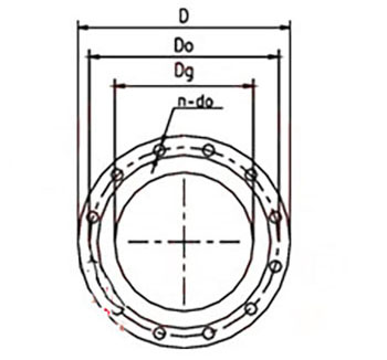
| Size | Suction Flange | |||
| Model | Dg | Do | D | n-do |
| 11/2GC-5 | 40 | 115 | 145 | 4-φ18 |
| 2GC-5 | 50 | 125 | 160 | 4-φ18 |
| 21/2GC-6 | 65 | 145 | 180 | 8-φ18 |
Pump Head Equation:

P1: Inlet
Parameter Definitions and Installation Height Calculation
- P₂: Outlet pressure of the pump (MPa)
- Z₁: Vertical distance from inlet pressure gauge to pump shaft center (m)
- Z₂: Vertical distance from outlet pressure gauge to pump shaft center (m)
- V₁: Flow velocity at the inlet pressure measurement point (m/s)
- V₂: Flow velocity at the outlet pressure measurement point (m/s)
- ρ: Liquid density (kg/m³)
- g: Gravitational acceleration (9.8 m/s²)
- Hg: Pump installation height — the vertical distance from the pump shaft centerline to the inlet liquid level (m)
Explanation of Parameters in Installation Height Formula
- P₀: Atmospheric pressure or absolute pressure at the water surface (expressed in meters of water column)
- [NPSH]: Net Positive Suction Head required by the pump (m)
- P′: Vapor pressure of the pumped liquid (in meters of water column)
- Δh: Head loss in the suction piping (m)
Note:
If the calculated value of Hg is positive, the pump shaft center is above the inlet water level. If negative, the pump operates under suction lift conditions and special attention must be paid to prevent cavitation.
Operating Parameter Note
Pump flow rate (Q), head (H), and shaft power (N) depend on the actual pump speed. Performance parameters should be corrected accordingly based on real operating RPM.
Pump Head Equation:(2)

How to Select a Pump Model
- Selection of the pump model should be based on the required flow rate and head. Ensure
- that the operating conditions match the pump’s design specifications.
- Consider the medium temperature and the properties of the fluid being pumped.
- Check the installation site conditions such as elevation, layout, and environment.
- For critical systems requiring continuous operation, install standby pumps for added reliability.
Engineering Notes
- Not suitable for liquids containing solids or fibrous materials.
- Long pipeline systems should include non-return valves and pressure relief devices.
- Ensure adequate lubrication of bearing assembly during operation.
- Shaft alignment tolerance must be verified after installation.
Compliance & Quality Assurance
- Each pump undergoes comprehensive factory hydraulic performance testing.
- Hydrostatic pressure testing of casing assembly.
- Rotor dynamic balance inspection.
- Material traceability documentation is provided.
- Optional third-party inspection is available.
Safety Notice
- Do not operate the pump under dry-running conditions.
- Ensure the suction system is properly primed before startup.
- Disconnect power before performing maintenance.
- Do not exceed rated discharge pressure.
OEM & Customization
- Chaodun Pump offers OEM and ODM customization for the GC Series pump. Options include stainless steel or cast iron materials, custom labeling, flange configurations, and performance adjustments.
- Technical adjustments can be made according to system requirements and installation conditions.
FAQs
- Q: What is the maximum allowable working temperature?
A: The maximum allowable temperature is 110°C, with higher temperature options available upon request. - Q: What is the maximum allowable solid size?
A: The pump is not suitable for handling solids. Only clean water or non-corrosive liquids should be used. - Q: What sealing options are available?
A: Mechanical seals and packing seals are available, depending on the application requirements. - Q: Can the pump operate under variable frequency control?
A: Yes, the pump can operate under VFD control, as long as the operating conditions remain within the pump’s design specifications. - Q: What certifications are available for the pumps?
A: The pumps are ISO9001 certified, and each unit undergoes extensive testing for performance verification before shipment. - Q: Is customization available for the GC series?
A: Yes, customization options include adjustments to flow rate, head, materials, and other technical parameters to meet specific application needs.