Product Overview
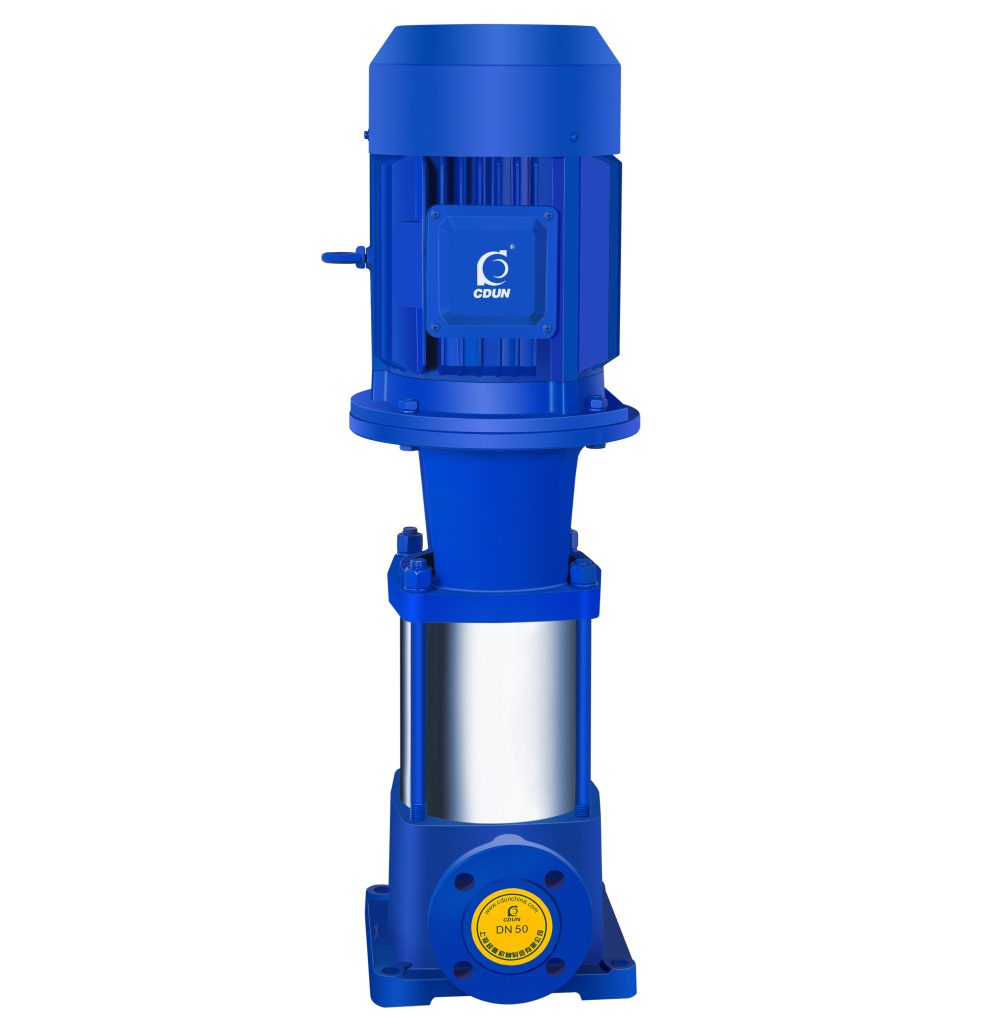
GDL Vertical Multistage Centrifugal Pump is an inline vertical high-pressure multistage pump designed for building water supply and industrial boosting systems.
It is engineered to deliver stable high head and constant pressure under continuous-duty operation where pipeline boosting and elevation lifting are required.
It is typically applied in high-rise water supply, fire-fighting booster systems, HVAC circulation and industrial process water transfer.
Model Designation
 Application
- High-rise building secondary water supply with rooftop tank boosting
- Fire pipeline pressurization systems requiring vertical inline installation
- HVAC chilled and hot water circulation loops
- Industrial clean water transfer with pressure stabilization demand
- Municipal pipeline pressure compensation stations
Engineering Advantages
- Vertical inline structure minimizes footprint and aligns with pipeline layout, reducing installation complexity and civil cost.
- Multistage impeller hydraulic design enables high head output under moderate motor power consumption.
- Coaxial suction and discharge configuration ensures hydraulic balance and stable axial load distribution.
- Cartridge-type mechanical seal simplifies maintenance and reduces downtime.
- Smooth performance curve supports stable operation near rated duty point.
System Components
GDL Vertical Multistage Centrifugal Pump:
- Electric motor (TEFC or equivalent standard motor)
- Pump shaft and multistage impeller assembly
- Diffuser and stage casing sections
- Mechanical seal assembly
- Pump head and base
- Inlet and outlet flanges (inline configuration)
The structure adopts sectional stage assembly with tie-bolt compression for pressure containment.
Technical Specifications
Service Conditions
- Medium: Clean water or non-corrosive liquids with similar physical and chemical properties to water
- Maximum ambient temperature: 40°C
- Installation: Indoor vertical installation
- Continuous-duty operation (S1)
Operating Conditions
Flow rate: 2 – 160 m³/h
Head: 24 – 200 m
Power range: 1.1 – 90kW
Speed: 2900 rpm
Liquid temperature: ≤ 80°C (standard), higher temp. available
Working pressure: ≤ 2.5 MPa
Detailed parameter tables are provided below.
Installation & Dimensions
Outline Drawing
 |
Serial No. | Name | Serial No. | Name |
| 1 | Pump Body | 11 | Coupling | |
| 2 | Tightening Bolt | 12 | Connecting Seat | |
| 3 | Outer Casing | 13 | Air Nozzle | |
| 4 | Impeller | 14 | Mechanical Seal | |
| 5 | Impeller Sleeve | 15 | Shaft | |
| 6 | Shaft Sleeve | 16 | Middle Section | |
| 7 | Seal Gasket | 17 | Shaft Sleeve Nut | |
| 8 | Nut | 18 | Sleeve Bearing | |
| 9 | Pin | 19 | Return Pipe Assembly | |
| 10 | Motor |
Performance Curves

Performance Parameters
| Model | Stages | Flow | Head | Speed | Motor Power | Efficiency | Required NPSH | Weight |
| m3/h | M | r/min | kw | % | NPSH | KG | ||
| 25GDL2-12 | 3 | 2 | 36 | 2900 | 1.1 | 30 | 2.9 | 58 |
| 25GDL2-12 | 4 | 2 | 48 | 2900 | 1.1 | 30 | 2.9 | 62 |
| 25GDL2-12 | 5 | 2 | 60 | 2900 | 2 | 30 | 2.9 | 68 |
| 25GDL2-12 | 6 | 2 | 72 | 2900 | 2 | 30 | 2.9 | 72 |
| 25GDL2-12 | 7 | 2 | 84 | 2900 | 2 | 30 | 2.9 | 78 |
| 25GDL2-12 | 8 | 2 | 96 | 2900 | 2.2 | 30 | 2.9 | 82 |
| 25GDL2-12 | 9 | 2 | 108 | 2900 | 2 | 30 | 2.9 | 86 |
| 25GDL2-12 | 10 | 2 | 120 | 2900 | 3 | 30 | 2.9 | 98 |
| 25GDL2-12 | 11 | 2 | 132 | 2900 | 3 | 30 | 2.9 | 102 |
| 25GDL2-12 | 12 | 2 | 144 | 2900 | 3 | 30 | 2.9 | |
| 25GDL2-12 | 13 | 2 | 156 | 2900 | 4 | 30 | 2.9 | |
| 25GDL2-12 | 14 | 2 | 168 | 2900 | 4 | 30 | 2.9 | |
| 25GDL2-12 | 15 | 2 | 180 | 2900 | 4 | 30 | 2.9 | |
| Model | Stages | Flow | Head | Speed | Motor Power | Efficiency | Required NPSH | Weight |
| m3/h | M | r/min | kw | % | NPSH | KG | ||
| 25GDL4-11 | 3 | 4 | 33 | 2900 | 1.1 | 42 | 2.9 | 58 |
| 25GDL4-11 | 4 | 4 | 44 | 2900 | 1.5 | 42 | 2.9 | 65 |
| 25GDL4-11 | 5 | 4 | 55 | 2900 | 2.2 | 42 | 2.9 | 72 |
| 25GDL4-11 | 6 | 4 | 66 | 2900 | 2.2 | 42 | 2.9 | 76 |
| 25GDL4-11 | 7 | 4 | 77 | 2900 | 3 | 42 | 2.9 | 86 |
| 25GDL4-11 | 8 | 4 | 88 | 2900 | 3 | 42 | 2.9 | 90 |
| 25GDL4-11 | 9 | 4 | 99 | 2900 | 3 | 42 | 2.9 | 94 |
| 25GDL4-11 | 10 | 4 | 110 | 2900 | 4 | 42 | 2.9 | 110 |
| 25GDL4-11 | 11 | 4 | 121 | 2900 | 4 | 42 | 2.9 | 114 |
| 25GDL4-11 | 12 | 4 | 132 | 2900 | 4 | 42 | 2.9 | |
| 25GDL4-11 | 13 | 4 | 143 | 2900 | 4 | 42 | 2.9 | |
| 25GDL4-11 | 14 | 4 | 154 | 2900 | 5.5 | 42 | 2.9 | |
| 25GDL4-11 | 15 | 4 | 165 | 2900 | 5.5 | 42 | 2.9 | |
| Model | Stages | Flow | Head | Speed | Motor Power | Efficiency | Required NPSH | Weight |
| m3/h | M | r/min | kw | % | NPSH | KG | ||
| 40GDL6-12 | 3 | 6 | 36 | 2900 | 1.5 | 52 | 2.9 | 72 |
| 40GDL6-12 | 4 | 6 | 48 | 2900 | 2.2 | 52 | 2.9 | 78 |
| 40GDL6-12 | 5 | 6 | 60 | 2900 | 2.2 | 52 | 2.9 | 82 |
| 40GDL6-12 | 6 | 6 | 72 | 2900 | 3 | 52 | 2.9 | 92 |
| 40GDL6-12 | 7 | 6 | 84 | 2900 | 3 | 52 | 2.9 | 96 |
| 40GDL6-12 | 8 | 6 | 96 | 2900 | 4 | 52 | 2.9 | 112 |
| 40GDL6-12 | 9 | 6 | 108 | 2900 | 4 | 52 | 2.9 | 116 |
| 40GDL6-12 | 10 | 6 | 120 | 2900 | 4 | 52 | 2.9 | 120 |
| 40GDL6-12 | 11 | 6 | 132 | 2900 | 5.5 | 52 | 2.9 | 140 |
| 40GDL6-12 | 12 | 6 | 144 | 2900 | 5.5 | 52 | 2.9 | |
| 40GDL6-12 | 13 | 6 | 156 | 2900 | 7.5 | 52 | 2.9 | |
| 40GDL6-12 | 14 | 6 | 168 | 2900 | 7.5 | 52 | 2.9 | |
| 40GDL6-12 | 15 | 6 | 180 | 2900 | 7.5 | 52 | 2.9 | |
| Model | Stages | Flow | Head | Speed | Motor Power | Efficiency | Required NPSH | Weight |
| m3/h | M | r/min | kw | % | NPSH | KG | ||
| 50GDL12-15 | 2 | 12 | 30 | 2900 | 2.2 | 57 | 3.5 | 113 |
| 50GDL12-15 | 3 | 12 | 45 | 2900 | 3 | 57 | 3.5 | 129 |
| 50GDL12-15 | 4 | 12 | 60 | 2900 | 4 | 57 | 3.5 | 149 |
| 50GDL12-15 | 5 | 12 | 75 | 2900 | 5.5 | 57 | 3.5 | 181 |
| 50GDL12-15 | 6 | 12 | 90 | 2900 | 5.5 | 57 | 3.5 | 190 |
| 50GDL12-15 | 7 | 12 | 105 | 2900 | 7.5 | 57 | 3.5 | 204 |
| 50GDL12-15 | 8 | 12 | 120 | 2900 | 7.5 | 57 | 3.5 | 212 |
| 50GDL12-15 | 9 | 12 | 135 | 2900 | 11 | 57 | 3.5 | 265 |
| 50GDL12-15 | 10 | 12 | 150 | 2900 | 11 | 57 | 3.5 | 273 |
| Model | Stages | Flow | Head | Speed | Motor Power | Efficiency | Required NPSH | Weight |
| m3/h | M | r/min | kw | % | NPSH | KG | ||
| 50GDL18-15 | 2 | 18 | 30 | 2900 | 3 | 63 | 4.0 | 122 |
| 50GDL18-15 | 3 | 18 | 45 | 2900 | 4 | 63 | 4.0 | 142 |
| 50GDL18-15 | 4 | 18 | 60 | 2900 | 5.5 | 63 | 4.0 | 175 |
| 50GDL18-15 | 5 | 18 | 75 | 2900 | 7.5 | 63 | 4.0 | 189 |
| 50GDL18-15 | 6 | 18 | 90 | 2900 | 7.5 | 63 | 4.0 | 198 |
| 50GDL18-15 | 7 | 18 | 105 | 2900 | 11 | 63 | 4.0 | 252 |
| 50GDL18-15 | 8 | 18 | 120 | 2900 | 11 | 63 | 4.0 | 261 |
| 50GDL18-15 | 9 | 18 | 135 | 2900 | 15 | 63 | 4.0 | 280 |
| 50GDL18-15 | 10 | 18 | 150 | 2900 | 15 | 63 | 4.0 | 289 |
| Model | Stages | Flow | Head | Speed | Motor Power | Efficiency | Required NPSH | Weight |
| m3/h | M | r/min | kw | % | NPSH | KG | ||
| 65GDL24-12 | 2 | 24 | 24 | 2900 | 3 | 63 | 4.0 | 122 |
| 65GDL24-12 | 3 | 24 | 36 | 2900 | 4 | 63 | 4.0 | 142 |
| 65GDL24-12 | 4 | 24 | 48 | 2900 | 5.5 | 63 | 4.0 | 175 |
| 65GDL24-12 | 5 | 24 | 60 | 2900 | 7.5 | 63 | 4.0 | 189 |
| 65GDL24-12 | 6 | 24 | 72 | 2900 | 7.5 | 63 | 4.0 | 252 |
| 65GDL24-12 | 7 | 24 | 84 | 2900 | 11 | 63 | 4.0 | 261 |
| 65GDL24-12 | 8 | 24 | 96 | 2900 | 11 | 63 | 4.0 | 280 |
| 65GDL24-12 | 9 | 24 | 108 | 2900 | 15 | 63 | 4.0 | 289 |
| 65GDL24-12 | 10 | 24 | 120 | 2900 | 15 | 63 | 4.0 | 298 |
| 65GDL24-12 | 11 | 24 | 132 | 2900 | 15 | 63 | 4.0 | 317 |
| 65GDL24-12 | 12 | 24 | 144 | 2900 | 18.5 | 63 | 4.0 | 346 |
| Model | Stages | Flow | Head | Speed | Motor Power | Efficiency | Required NPSH | Weight |
| m3/h | M | r/min | kw | % | NPSH | KG | ||
| 80GDL36-12 | 2 | 36 | 24 | 2900 | 4 | 71 | 4.2 | 193 |
| 80GDL36-12 | 3 | 36 | 36 | 2900 | 5.5 | 71 | 4.2 | 227 |
| 80GDL36-12 | 4 | 36 | 48 | 2900 | 7.5 | 71 | 4.2 | 244 |
| 80GDL36-12 | 5 | 36 | 60 | 2900 | 11 | 71 | 4.2 | 292 |
| 80GDL36-12 | 6 | 36 | 72 | 2900 | 11 | 71 | 4.2 | 302 |
| 80GDL36-12 | 7 | 36 | 84 | 2900 | 15 | 71 | 4.2 | 322 |
| 80GDL36-12 | 8 | 36 | 96 | 2900 | 15 | 71 | 4.2 | 332 |
| 80GDL36-12 | 9 | 36 | 108 | 2900 | 18.5 | 71 | 4.2 | 365 |
| 80GDL36-12 | 10 | 36 | 120 | 2900 | 18.5 | 71 | 4.2 | 375 |
| Model | Stages | Flow | Head | Speed | Motor Power | Efficiency | Required NPSH | Weight |
| m3/h | M | r/min | kw | % | NPSH | KG | ||
| 80GDL54-14 | 2 | 54 | 28 | 2900 | 7.5 | 73 | 4.0 | 218 |
| 80GDL54-14 | 3 | 54 | 42 | 2900 | 11 | 73 | 4.0 | 267 |
| 80GDL54-14 | 4 | 54 | 56 | 2900 | 15 | 73 | 4.0 | 287 |
| 80GDL54-14 | 5 | 54 | 70 | 2900 | 18.5 | 73 | 4.0 | 320 |
| 80GDL54-14 | 6 | 54 | 84 | 2900 | 18.5 | 73 | 4.0 | 330 |
| 80GDL54-14 | 7 | 54 | 98 | 2900 | 22 | 73 | 4.0 | 373 |
| 80GDL54-14 | 8 | 54 | 112 | 2900 | 30 | 73 | 4.0 | 400 |
| 80GDL54-14 | 9 | 54 | 126 | 2900 | 30 | 73 | 4.0 | 421 |
| 80GDL54-14 | 10 | 54 | 140 | 2900 | 37 | 73 | 4.0 | 432 |
| Model | Stages | Flow | Head | Speed | Motor Power | Efficiency | Required NPSH | Weight |
| m3/h | M | r/min | kw | % | NPSH | KG | ||
| 100GDL72-14 | 2 | 72 | 28 | 2900 | 11 | 73 | 4.5 | 276 |
| 100GDL72-14 | 3 | 72 | 42 | 2900 | 15 | 73 | 4.5 | 298 |
| 100GDL72-14 | 4 | 72 | 56 | 2900 | 18.5 | 73 | 4.5 | 336 |
| 100GDL72-14 | 5 | 72 | 70 | 2900 | 22 | 73 | 4.5 | 381 |
| 100GDL72-14 | 6 | 72 | 84 | 2900 | 30 | 73 | 4.5 | 453 |
| 100GDL72-14 | 7 | 72 | 98 | 2900 | 30 | 73 | 4.5 | 466 |
| 100GDL72-14 | 8 | 72 | 112 | 2900 | 37 | 73 | 4.5 | 493 |
| 100GDL72-14 | 9 | 72 | 126 | 2900 | 37 | 73 | 4.5 | 582 |
| 100GDL72-14 | 10 | 72 | 140 | 2900 | 45 | 73 | 4.5 | 595 |
| Model | Stages | Flow | Head | Speed | Motor Power | Efficiency | Required NPSH | Weight |
| m3/h | M | r/min | kw | % | NPSH | KG | ||
| 100GDL100-20 | 2 | 108 | 40 | 2900 | 18.5 | 74 | 4.5 | 292 |
| 100GDL100-20 | 3 | 108 | 60 | 2900 | 30 | 74 | 4.5 | 430 |
| 100GDL100-20 | 4 | 108 | 80 | 2900 | 37 | 74 | 4.5 | 463 |
| 100GDL100-20 | 5 | 108 | 100 | 2900 | 45 | 74 | 4.5 | 555 |
| 100GDL100-20 | 6 | 108 | 120 | 2900 | 55 | 74 | 4.5 | 640 |
| 100GDL100-20 | 7 | 108 | 140 | 2900 | 75 | 74 | 4.5 | 840 |
| 100GDL100-20 | 8 | 108 | 160 | 2900 | 75 | 74 | 4.5 | 855 |
| 100GDL100-20 | 9 | 108 | 180 | 2900 | 90 | 74 | 4.5 | 870 |
| 100GDL100-20 | 10 | 108 | 200 | 2900 | 90 | 74 | 4.5 | 955 |
| Model | Stages | Flow | Head | Speed | Motor Power | Efficiency | Required NPSH | Weight |
| m3/h | M | r/min | kw | % | NPSH | KG | ||
| 125GDL100-20 | 2 | 108 | 40 | 2900 | 18.5 | 74 | 4.5 | 292 |
| 125GDL100-20 | 3 | 108 | 60 | 2900 | 30 | 74 | 4.5 | 430 |
| 125GDL100-20 | 4 | 108 | 80 | 2900 | 37 | 74 | 4.5 | 463 |
| 125GDL100-20 | 5 | 108 | 100 | 2900 | 45 | 74 | 4.5 | 555 |
| 125GDL100-20 | 6 | 108 | 120 | 2900 | 55 | 74 | 4.5 | 640 |
| 125GDL100-20 | 7 | 108 | 140 | 2900 | 75 | 74 | 4.5 | 840 |
| 125GDL100-20 | 8 | 108 | 160 | 2900 | 75 | 74 | 4.5 | 855 |
| 125GDL100-20 | 9 | 108 | 180 | 2900 | 90 | 74 | 4.5 | 870 |
| 125GDL100-20 | 10 | 108 | 200 | 2900 | 90 | 74 | 4.5 | 955 |
| Model | Stages | Flow | Head | Speed | Motor Power | Efficiency | Required NPSH | Weight |
| m3/h | M | r/min | kw | % | NPSH | KG | ||
| 150GDL160-20 | 2 | 160 | 40 | 2900 | 30 | 78 | 4.5 | 422 |
| 150GDL160-20 | 3 | 160 | 60 | 2900 | 37 | 78 | 4.5 | 452 |
| 150GDL160-20 | 4 | 160 | 80 | 2900 | 55 | 78 | 4.5 | 613 |
| 150GDL160-20 | 5 | 160 | 100 | 2900 | 75 | 78 | 4.5 | 820 |
| 150GDL160-20 | 6 | 160 | 120 | 2900 | 75 | 78 | 4.5 | 836 |
| 150GDL160-20 | 7 | 160 | 140 | 2900 | 90 | 78 | 4.5 | 922 |
Installation Dimensions

Performance Data |
|||||||
| Model | H1 | L | B | 4-φd1 | Inlet Flange (J) | ||
| DN | N-φD2 | φD | |||||
| 25GDL | 60 | 300 | 200 | 4-φ18 | 25 | 4-φ14 | 85 |
| 40GDL | 80 | 360 | 235 | 4-φ18 | 40 | 4-φ18 | 110 |
| 50GDL | 100 | 360 | 235 | 4-φ18 | 50 | 4-φ18 | 125 |
| 65GDL | 110 | 360 | 235 | 4-φ18 | 65 | 4-φ18 | 145 |
| 80GDL | 130 | 420 | 300 | 4-φ18 | 80 | 8-φ18 | 160 |
| 100GDL | 160 | 520 | 350 | 4-φ18 | 100 | 8-φ18 | 180 |
| 125GDL | 160 | 500 | 400 | 4-φ18 | 125 | 8-φ18 | 210 |
| 150GDL | 180 | 600 | 400 | 4-φ18 | 150 | 8-φ22 | 245 |
How to Select a Pump Model
- Confirm required flow rate (m³/h) under peak and normal operating conditions.
- Determine total dynamic head including elevation difference and pipeline loss.
- Verify system working pressure does not exceed 2.5 MPa.
- Select motor power based on duty point within high-efficiency range of performance curve.
- Confirm medium temperature and compatibility with standard seal configuration.
Engineering Notes
- The GDL pump is not designed for liquids containing solid particles or fibers.
- Operation below minimum flow may cause overheating and seal damage.
- Parallel pump configuration is recommended for variable load conditions.
- Ensure NPSH available exceeds required value to avoid cavitation.
Compliance & Quality Assurance
- Factory hydraulic performance test before shipment
- Pressure containment test for pump casing
- Rotor dynamic balance verification
- Mechanical seal inspection and leakage test
- Material traceability documentation available upon request
- Optional third-party inspection prior to dispatch
Safety Notice
- Do not operate under dry-running condition
- Ensure suction priming before startup
- Disconnect power before maintenance
- Do not exceed rated working pressure
OEM & Customization
This pump series supports engineered configuration and duty-based matching. Technical adjustments can be made according to system requirements and installation conditions.
Available options include:
• Motor voltage & frequency
• Mechanical seal type and configuration
• Wetted parts material selection
• Surface coating and corrosion protection
Configuration is determined based on duty point and project specifications.
FAQs
Q: Can the GDL pump operate under VFD control?
A: Yes, frequency conversion is allowed provided operation remains within rated performance curve range.
Q: What is the maximum allowable working pressure?
A: The maximum working pressure is 2.5 MPa.
Q: What type of mechanical seal is used?
A: Standard single mechanical seal; cartridge or high-temperature variants are optional.
Q: Is the pump suitable for hot water circulation?
A: Standard version supports ≤80°C; higher temperature configuration is available.
Q: Can the pump be installed outdoors?
A: Standard configuration is for indoor installation; outdoor use requires protective enclosure.
Q: How is cavitation avoided in this pump?
A: Ensure adequate NPSH available and avoid operation below minimum flow rate.
Q: Can multiple pumps operate in parallel?
A: Yes, parallel configuration is recommended for large flow demand systems.