Product Overview
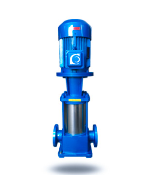
The GDL vertical multistage clean-water pump is a vertical inline multistage centrifugal pump, designed and manufactured in line with widely adopted international product concepts. It features a compact structure, low weight, small footprint, and stable operation with relatively low vibration and noise. It is suitable for conveying clean water and liquids with physical and chemical properties similar to water, and is intended for system retrofit and replacement applications.
Model Designation

Key Features
-
Vertical construction: Small installation footprint; the center of gravity is aligned with the base center, supporting smooth operation, low vibration, and extended service life.
-
Inline, equal-size nozzles: Suction and discharge nozzles are the same diameter and arranged coaxially, simplifying piping connection and installation.
-
Optional motor rain cover: Supports outdoor installation and reduces the need for a pump room.
-
Configurable stage count: Pump head can be configured by adjusting the number of stages to meet different system requirements and operating ranges.
-
Hard-alloy mechanical seal: Reliable sealing performance with low leakage risk and reduced mechanical wear.
-
High efficiency / energy-saving: Designed for efficient operation and reduced energy consumption; clean appearance.
-
DN50 and above: For nominal sizes above DN50, internal components adopt a cast construction.
Engineering Summary
The impeller, guide components, and pump casing are manufactured using stainless-steel stamping, forming, and welding processes. The pump is equipped with a hard-alloy mechanical seal and guide bearing, supporting high efficiency, energy-saving performance, and extended service life.
Typical Applications
Suitable for boiler feedwater systems and also used for: pressure-vessel water supply, hot-water circulation, high-rise building water supply, agricultural irrigation, fire-fighting systems, hydro cleaning, food processing, stamping, pharmaceuticals, chemical industry, aquaculture, environmental protection, chemical processing, and machine-tool cooling systems.
System Configuration
The pump is designed for vertical installation and is suited to inline piping systems. The suction and discharge nozzles are equal in diameter and coaxially aligned to enable inline installation, typically without modifying existing piping layout. The motor can be fitted with an optional rain cover to support outdoor installation.
Components & Supply
-
Pump casing / pipe section (stainless-steel stamped, formed, and welded construction)
-
Shaft assembly
-
Guide assembly (guide vanes / diffuser)
-
Shaft sealing system: hard-alloy mechanical seal
-
Guide bearing
-
Motor assembly (optional rain cover)
-
For DN50 and above: internal components with cast construction
Technical Service
The pump adopts a vertical installation design. The center of gravity is aligned with the pump base center to support smooth running and reduced vibration. The suction and discharge nozzles are of equal diameter and arranged on the same horizontal centerline for inline installation, typically without changing the existing piping layout. An optional motor rain cover is available to facilitate outdoor installation and reduce pump-room construction requirements, thereby lowering infrastructure investment.
Operating Conditions
-
Medium: clean water or liquids with physical and chemical properties similar to water
-
Medium requirements: free of solid particles and fibers; non-corrosive and non-explosive
-
Maximum liquid temperature: 120 °C
-
Maximum working pressure: 2.5 MPa
-
Power supply: three-phase 380 V, 50 Hz; voltage fluctuation within ±5%
Service Conditions
-
Ambient temperature: ≤40 °C
-
Relative humidity: ≤95%
Protection Functions
(No specific items provided in the original text.)
Selection Criteria
Selection should be based on system requirements and site conditions. Verify:
-
The medium meets the requirements (clean, free of particles/fibers, non-corrosive, non-explosive).
-
Liquid temperature ≤120 °C and system working pressure ≤2.5 MPa.
-
Power supply is three-phase 380 V / 50 Hz with voltage fluctuation within ±5%.
-
Site environment meets ambient temperature ≤40 °C and relative humidity ≤95%.
-
Match the required operating range by configuring the number of stages according to system duty conditions.
Installation & Dimensions
Outline Drawing

Performance Data
| No. | Name | No. | Name |
| 1 | Pump Body | 11 | Coupling |
| 2 | Tightening Bolt | 12 | Connecting Seat |
| 3 | Outer Casing | 13 | Air Vent |
| 4 | Impeller | 14 | Mechanical Seal |
| 5 | Impeller Sleeve | 15 | Shaft |
| 6 | Shaft Sleeve | 16 | Intermediate Section |
| 7 | Gasket | 17 | Shaft Sleeve Nut |
| 8 | Nut | 18 | Bearing Bush |
| 9 | Key | 19 | Return Pipe Assembly |
| 10 | Motor |
Performance Curves

Performance Parameters
| Model | Stages | Flow Rate | Head | Speed | Motor Power | Efficiency | NPSH (Required) | Weight |
| m³/h | m | r/min | kW | % | NPSH | kg | ||
| 25GDL2-12 | 3 | 2 | 36 | 2900 | 1.1 | 30 | 2.9 | 58 |
| 25GDL2-12 | 4 | 2 | 48 | 2900 | 1.1 | 30 | 2.9 | 62 |
| 25GDL2-12 | 5 | 2 | 60 | 2900 | 2 | 30 | 2.9 | 68 |
| 25GDL2-12 | 6 | 2 | 72 | 2900 | 2 | 30 | 2.9 | 72 |
| 25GDL2-12 | 7 | 2 | 84 | 2900 | 2 | 30 | 2.9 | 78 |
| 25GDL2-12 | 8 | 2 | 96 | 2900 | 2.2 | 30 | 2.9 | 82 |
| 25GDL2-12 | 9 | 2 | 108 | 2900 | 2 | 30 | 2.9 | 86 |
| 25GDL2-12 | 10 | 2 | 120 | 2900 | 3 | 30 | 2.9 | 98 |
| 25GDL2-12 | 11 | 2 | 132 | 2900 | 3 | 30 | 2.9 | 102 |
| 25GDL2-12 | 12 | 2 | 144 | 2900 | 3 | 30 | 2.9 | |
| 25GDL2-12 | 13 | 2 | 156 | 2900 | 4 | 30 | 2.9 | |
| 25GDL2-12 | 14 | 2 | 168 | 2900 | 4 | 30 | 2.9 | |
| 25GDL2-12 | 15 | 2 | 180 | 2900 | 4 | 30 | 2.9 | |
| Model | Stages | Flow Rate | Head | Speed | Motor Power | Efficiency | NPSH (Required) | Weight |
| m³/h | m | r/min | kW | % | NPSH | kg | ||
| 25GDL4-11 | 3 | 4 | 33 | 2900 | 1.1 | 42 | 2.9 | 58 |
| 25GDL4-11 | 4 | 4 | 44 | 2900 | 1.5 | 42 | 2.9 | 65 |
| 25GDL4-11 | 5 | 4 | 55 | 2900 | 2.2 | 42 | 2.9 | 72 |
| 25GDL4-11 | 6 | 4 | 66 | 2900 | 2.2 | 42 | 2.9 | 76 |
| 25GDL4-11 | 7 | 4 | 77 | 2900 | 3 | 42 | 2.9 | 86 |
| 25GDL4-11 | 8 | 4 | 88 | 2900 | 3 | 42 | 2.9 | 90 |
| 25GDL4-11 | 9 | 4 | 99 | 2900 | 3 | 42 | 2.9 | 94 |
| 25GDL4-11 | 10 | 4 | 110 | 2900 | 4 | 42 | 2.9 | 110 |
| 25GDL4-11 | 11 | 4 | 121 | 2900 | 4 | 42 | 2.9 | 114 |
| 25GDL4-11 | 12 | 4 | 132 | 2900 | 4 | 42 | 2.9 | |
| 25GDL4-11 | 13 | 4 | 143 | 2900 | 4 | 42 | 2.9 | |
| 25GDL4-11 | 14 | 4 | 154 | 2900 | 5.5 | 42 | 2.9 | |
| 25GDL4-11 | 15 | 4 | 165 | 2900 | 5.5 | 42 | 2.9 | |
| Model | Stages | Flow Rate | Head | Speed | Motor Power | Efficiency | NPSH (Required) | Weight |
| m³/h | m | r/min | kW | % | NPSH | kg | ||
| 40GDL6-12 | 3 | 6 | 36 | 2900 | 1.5 | 52 | 2.9 | 72 |
| 40GDL6-12 | 4 | 6 | 48 | 2900 | 2.2 | 52 | 2.9 | 78 |
| 40GDL6-12 | 5 | 6 | 60 | 2900 | 2.2 | 52 | 2.9 | 82 |
| 40GDL6-12 | 6 | 6 | 72 | 2900 | 3 | 52 | 2.9 | 92 |
| 40GDL6-12 | 7 | 6 | 84 | 2900 | 3 | 52 | 2.9 | 96 |
| 40GDL6-12 | 8 | 6 | 96 | 2900 | 4 | 52 | 2.9 | 112 |
| 40GDL6-12 | 9 | 6 | 108 | 2900 | 4 | 52 | 2.9 | 116 |
| 40GDL6-12 | 10 | 6 | 120 | 2900 | 4 | 52 | 2.9 | 120 |
| 40GDL6-12 | 11 | 6 | 132 | 2900 | 5.5 | 52 | 2.9 | 140 |
| 40GDL6-12 | 12 | 6 | 144 | 2900 | 5.5 | 52 | 2.9 | |
| 40GDL6-12 | 13 | 6 | 156 | 2900 | 7.5 | 52 | 2.9 | |
| 40GDL6-12 | 14 | 6 | 168 | 2900 | 7.5 | 52 | 2.9 | |
| 40GDL6-12 | 15 | 6 | 180 | 2900 | 7.5 | 52 | 2.9 | |
| Model | Stages | Flow Rate | Head | Speed | Motor Power | Efficiency | NPSH (Required) | Weight |
| m³/h | m | r/min | kW | % | NPSH | kg | ||
| 50GDL12-15 | 2 | 12 | 30 | 2900 | 2.2 | 57 | 3.5 | 113 |
| 50GDL12-15 | 3 | 12 | 45 | 2900 | 3 | 57 | 3.5 | 129 |
| 50GDL12-15 | 4 | 12 | 60 | 2900 | 4 | 57 | 3.5 | 149 |
| 50GDL12-15 | 5 | 12 | 75 | 2900 | 5.5 | 57 | 3.5 | 181 |
| 50GDL12-15 | 6 | 12 | 90 | 2900 | 5.5 | 57 | 3.5 | 190 |
| 50GDL12-15 | 7 | 12 | 105 | 2900 | 7.5 | 57 | 3.5 | 204 |
| 50GDL12-15 | 8 | 12 | 120 | 2900 | 7.5 | 57 | 3.5 | 212 |
| 50GDL12-15 | 9 | 12 | 135 | 2900 | 11 | 57 | 3.5 | 265 |
| 50GDL12-15 | 10 | 12 | 150 | 2900 | 11 | 57 | 3.5 | 273 |
| Model | Stages | Flow Rate | Head | Speed | Motor Power | Efficiency | NPSH (Required) | Weight |
| m³/h | m | r/min | kW | % | NPSH | kg | ||
| 50GDL18-15 | 2 | 18 | 30 | 2900 | 3 | 63 | 4.0 | 122 |
| 50GDL18-15 | 3 | 18 | 45 | 2900 | 4 | 63 | 4.0 | 142 |
| 50GDL18-15 | 4 | 18 | 60 | 2900 | 5.5 | 63 | 4.0 | 175 |
| 50GDL18-15 | 5 | 18 | 75 | 2900 | 7.5 | 63 | 4.0 | 189 |
| 50GDL18-15 | 6 | 18 | 90 | 2900 | 7.5 | 63 | 4.0 | 198 |
| 50GDL18-15 | 7 | 18 | 105 | 2900 | 11 | 63 | 4.0 | 252 |
| 50GDL18-15 | 8 | 18 | 120 | 2900 | 11 | 63 | 4.0 | 261 |
| 50GDL18-15 | 9 | 18 | 135 | 2900 | 15 | 63 | 4.0 | 280 |
| 50GDL18-15 | 10 | 18 | 150 | 2900 | 15 | 63 | 4.0 | 289 |
| Model | Stages | Flow Rate | Head | Speed | Motor Power | Efficiency | NPSH (Required) | Weight |
| m³/h | m | r/min | kW | % | NPSH | kg | ||
| 65GDL24-12 | 2 | 24 | 24 | 2900 | 3 | 63 | 4.0 | 122 |
| 65GDL24-12 | 3 | 24 | 36 | 2900 | 4 | 63 | 4.0 | 142 |
| 65GDL24-12 | 4 | 24 | 48 | 2900 | 5.5 | 63 | 4.0 | 175 |
| 65GDL24-12 | 5 | 24 | 60 | 2900 | 7.5 | 63 | 4.0 | 189 |
| 65GDL24-12 | 6 | 24 | 72 | 2900 | 7.5 | 63 | 4.0 | 252 |
| 65GDL24-12 | 7 | 24 | 84 | 2900 | 11 | 63 | 4.0 | 261 |
| 65GDL24-12 | 8 | 24 | 96 | 2900 | 11 | 63 | 4.0 | 280 |
| 65GDL24-12 | 9 | 24 | 108 | 2900 | 15 | 63 | 4.0 | 289 |
| 65GDL24-12 | 10 | 24 | 120 | 2900 | 15 | 63 | 4.0 | 298 |
| 65GDL24-12 | 11 | 24 | 132 | 2900 | 15 | 63 | 4.0 | 317 |
| 65GDL24-12 | 12 | 24 | 144 | 2900 | 18.5 | 63 | 4.0 | 346 |
| Model | Stages | Flow Rate | Head | Speed | Motor Power | Efficiency | NPSH (Required) | Weight |
| m³/h | m | r/min | kW | % | NPSH | kg | ||
| 80GDL36-12 | 2 | 36 | 24 | 2900 | 4 | 71 | 4.2 | 193 |
| 80GDL36-12 | 3 | 36 | 36 | 2900 | 5.5 | 71 | 4.2 | 227 |
| 80GDL36-12 | 4 | 36 | 48 | 2900 | 7.5 | 71 | 4.2 | 244 |
| 80GDL36-12 | 5 | 36 | 60 | 2900 | 11 | 71 | 4.2 | 292 |
| 80GDL36-12 | 6 | 36 | 72 | 2900 | 11 | 71 | 4.2 | 302 |
| 80GDL36-12 | 7 | 36 | 84 | 2900 | 15 | 71 | 4.2 | 322 |
| 80GDL36-12 | 8 | 36 | 96 | 2900 | 15 | 71 | 4.2 | 332 |
| 80GDL36-12 | 9 | 36 | 108 | 2900 | 18.5 | 71 | 4.2 | 365 |
| 80GDL36-12 | 10 | 36 | 120 | 2900 | 18.5 | 71 | 4.2 | 375 |
| Model | Stages | Flow Rate | Head | Speed | Motor Power | Efficiency | NPSH (Required) | Weight |
| m³/h | m | r/min | kW | % | NPSH | kg | ||
| 80GDL54-14 | 2 | 54 | 28 | 2900 | 7.5 | 73 | 4.0 | 218 |
| 80GDL54-14 | 3 | 54 | 42 | 2900 | 11 | 73 | 4.0 | 267 |
| 80GDL54-14 | 4 | 54 | 56 | 2900 | 15 | 73 | 4.0 | 287 |
| 80GDL54-14 | 5 | 54 | 70 | 2900 | 18.5 | 73 | 4.0 | 320 |
| 80GDL54-14 | 6 | 54 | 84 | 2900 | 18.5 | 73 | 4.0 | 330 |
| 80GDL54-14 | 7 | 54 | 98 | 2900 | 22 | 73 | 4.0 | 373 |
| 80GDL54-14 | 8 | 54 | 112 | 2900 | 30 | 73 | 4.0 | 400 |
| 80GDL54-14 | 9 | 54 | 126 | 2900 | 30 | 73 | 4.0 | 421 |
| 80GDL54-14 | 10 | 54 | 140 | 2900 | 37 | 73 | 4.0 | 432 |
| Model | Stages | Flow Rate | Head | Speed | Motor Power | Efficiency | NPSH (Required) | Weight |
| m³/h | m | r/min | kW | % | NPSH | kg | ||
| 100GDL72-14 | 2 | 72 | 28 | 2900 | 11 | 73 | 4.5 | 276 |
| 100GDL72-14 | 3 | 72 | 42 | 2900 | 15 | 73 | 4.5 | 298 |
| 100GDL72-14 | 4 | 72 | 56 | 2900 | 18.5 | 73 | 4.5 | 336 |
| 100GDL72-14 | 5 | 72 | 70 | 2900 | 22 | 73 | 4.5 | 381 |
| 100GDL72-14 | 6 | 72 | 84 | 2900 | 30 | 73 | 4.5 | 453 |
| 100GDL72-14 | 7 | 72 | 98 | 2900 | 30 | 73 | 4.5 | 466 |
| 100GDL72-14 | 8 | 72 | 112 | 2900 | 37 | 73 | 4.5 | 493 |
| 100GDL72-14 | 9 | 72 | 126 | 2900 | 37 | 73 | 4.5 | 582 |
| 100GDL72-14 | 10 | 72 | 140 | 2900 | 45 | 73 | 4.5 | 595 |
| Model | Stages | Flow Rate | Head | Speed | Motor Power | Efficiency | NPSH (Required) | Weight |
| m³/h | m | r/min | kW | % | NPSH | kg | ||
| 100GDL100-20 | 2 | 108 | 40 | 2900 | 18.5 | 74 | 4.5 | 292 |
| 100GDL100-20 | 3 | 108 | 60 | 2900 | 30 | 74 | 4.5 | 430 |
| 100GDL100-20 | 4 | 108 | 80 | 2900 | 37 | 74 | 4.5 | 463 |
| 100GDL100-20 | 5 | 108 | 100 | 2900 | 45 | 74 | 4.5 | 555 |
| 100GDL100-20 | 6 | 108 | 120 | 2900 | 55 | 74 | 4.5 | 640 |
| 100GDL100-20 | 7 | 108 | 140 | 2900 | 75 | 74 | 4.5 | 840 |
| 100GDL100-20 | 8 | 108 | 160 | 2900 | 75 | 74 | 4.5 | 855 |
| 100GDL100-20 | 9 | 108 | 180 | 2900 | 90 | 74 | 4.5 | 870 |
| 100GDL100-20 | 10 | 108 | 200 | 2900 | 90 | 74 | 4.5 | 955 |
| Model | Stages | Flow Rate | Head | Speed | Motor Power | Efficiency | NPSH (Required) | Weight |
| m³/h | m | r/min | kW | % | NPSH | kg | ||
| 125GDL100-20 | 2 | 108 | 40 | 2900 | 18.5 | 74 | 4.5 | 292 |
| 125GDL100-20 | 3 | 108 | 60 | 2900 | 30 | 74 | 4.5 | 430 |
| 125GDL100-20 | 4 | 108 | 80 | 2900 | 37 | 74 | 4.5 | 463 |
| 125GDL100-20 | 5 | 108 | 100 | 2900 | 45 | 74 | 4.5 | 555 |
| 125GDL100-20 | 6 | 108 | 120 | 2900 | 55 | 74 | 4.5 | 640 |
| 125GDL100-20 | 7 | 108 | 140 | 2900 | 75 | 74 | 4.5 | 840 |
| 125GDL100-20 | 8 | 108 | 160 | 2900 | 75 | 74 | 4.5 | 855 |
| 125GDL100-20 | 9 | 108 | 180 | 2900 | 90 | 74 | 4.5 | 870 |
| 125GDL100-20 | 10 | 108 | 200 | 2900 | 90 | 74 | 4.5 | 955 |
| Model | Stages | Flow Rate | Head | Speed | Motor Power | Efficiency | NPSH (Required) | Weight |
| m³/h | m | r/min | kW | % | NPSH | kg | ||
| 150GDL160-20 | 2 | 160 | 40 | 2900 | 30 | 78 | 4.5 | 422 |
| 150GDL160-20 | 3 | 160 | 60 | 2900 | 37 | 78 | 4.5 | 452 |
| 150GDL160-20 | 4 | 160 | 80 | 2900 | 55 | 78 | 4.5 | 613 |
| 150GDL160-20 | 5 | 160 | 100 | 2900 | 75 | 78 | 4.5 | 820 |
| 150GDL160-20 | 6 | 160 | 120 | 2900 | 75 | 78 | 4.5 | 836 |
| 150GDL160-20 | 7 | 160 | 140 | 2900 | 90 | 78 | 4.5 | 922 |
Installation Diagram

Performance Data
| Model | H1 | L | B | 4-φd1 | Inlet Flange (J) | ||
| DN | N-φD2 | φD | |||||
| 25GDL | 60 | 300 | 200 | 4-φ18 | 25 | 4-φ14 | 85 |
| 40GDL | 80 | 360 | 235 | 4-φ18 | 40 | 4-φ18 | 110 |
| 50GDL | 100 | 360 | 235 | 4-φ18 | 50 | 4-φ18 | 125 |
| 65GDL | 110 | 360 | 235 | 4-φ18 | 65 | 4-φ18 | 145 |
| 80GDL | 130 | 420 | 300 | 4-φ18 | 80 | 8-φ18 | 160 |
| 100GDL | 160 | 520 | 350 | 4-φ18 | 100 | 8-φ18 | 180 |
| 125GDL | 160 | 500 | 400 | 4-φ18 | 125 | 8-φ18 | 210 |
| 150GDL | 180 | 600 | 400 | 4-φ18 | 150 | 8-φ22 | 245 |
Operating Manual
Precautions
-
The piping system must not transmit any weight or external force to the pump; otherwise, the pump may be damaged.
-
The pump and motor are an integrated unit and have been factory-aligned by the manufacturer prior to delivery. Therefore, no further alignment is required during installation, making installation more convenient.
-
Before installation, carefully inspect the flow passage for any hard foreign objects (e.g., stones, metal particles) to avoid damage to hydraulic components during operation.
-
The foundation bolts must be tightened during installation. After installation, inspect the pump periodically to prevent bolt loosening; loosened bolts may cause severe vibration during start-up and adversely affect performance.
-
For ease of maintenance and safe operation, install a regulating valve and a pressure gauge on both the inlet and outlet pipelines. For high-head applications, install a check valve upstream of the discharge gate valve to prevent water hammer and ensure safe operation during sudden power outages.
-
When the pump operates under suction conditions, a foot valve must be installed. The inlet pipeline must not have excessive bends and must be free from air or water leakage to avoid impairing suction performance.
-
To prevent impurities from entering the pump and clogging the flow passage, install a strainer upstream of the pump inlet.
-
Before installing the pipelines, rotate the pump rotor by hand. There should be no rubbing or jamming. If abnormal resistance is detected, disassemble the pump and identify the cause.
Preparatory Work
-
Rotate the coupling by hand; the impeller should rotate freely without friction.
-
Open the inlet valve and the air vent valve to completely fill the pump chamber with liquid, then close the air vent valve.
-
When pumping hot liquid, preheat the pump before start-up. The temperature rise rate must not exceed 50°C/h. Preheating is achieved by circulating the pumped liquid to ensure uniform heating of the pump.
-
Manually rotate the pump several turns to allow the lubricating water to reach the mechanical seal faces.
-
Jog the motor to confirm the correct direction of rotation.
Start-Up & Operation
-
Fully open the inlet valve and close the discharge valve.
-
Energize the motor. When the GDL multistage booster pump reaches rated speed, gradually open the discharge valve and adjust to the required operating condition.
-
Observe instrument readings and check seal leakage. Normal mechanical seal leakage is approximately 3 drops/min. Check the temperature of the motor and bearings (≤70°C). If any abnormal condition is found, stop the pump immediately and inspect the cause.
Shutdown
-
Gradually close the discharge valve.
-
Close the inlet valve.
-
If the ambient temperature is below 0°C, drain the liquid inside the pump to prevent freezing damage.
-
For long-term shutdown, disassemble, clean, and properly store the pump.
Equipment & Maintenance
-
The inlet pipeline must be well sealed and free from water or air leakage.
-
The pump must not operate under cavitation conditions for extended periods.
-
The pump must not run continuously at excessive flow where the motor may overload.
-
Regularly check the motor current and ensure the pump operates within its design range.
-
The pump should be monitored by a dedicated operator during operation.
-
Lubricate the bearings every 500 operating hours.
-
After long-term continuous operation, mechanical wear may increase noise and vibration. Stop the pump for inspection; replace worn parts and bearings if necessary. Major maintenance is generally recommended once per year.
Mechanical Seal Maintenance
-
The mechanical seal flushing liquid must be clean and free of solid particles.
-
Dry running of the mechanical seal is strictly prohibited.
-
Before start-up, rotate the pump (or motor) several turns to prevent start-up shock damage to the mechanical seal.
OEM & Custom
We offer OEM/ODM customization, including stainless steel materials, special voltages (220V/415V/460V), explosion-proof motors, and control panel integration. Optional flange standards (DIN/ANSI/JIS) and private labeling are supported. All products comply with ISO9001 and CE certification for export to global markets.
FAQs
- Q: What’s the main application of GDL pumps?
A: They are used in building water supply, HVAC, boiler feed, and clean water circulation systems. - Q: What temperature range can it handle?
A: Standard type ≤120°C, suitable for hot and cold clean water. - Q: What material options are available?
A: Standard stainless steel 304; optional 316L or cast iron versions are available. - Q: Can it operate under continuous duty?
A: Yes, it is designed for 24-hour operation with low noise and high reliability. - Q: What is the maximum system pressure?
A: Up to 2.0 MPa, depending on model configuration. - Q: How often should maintenance be done?
A: Bearings should be lubricated every 500 hours; mechanical seals inspected every 3–6 months. - Q: Which markets use this pump?
A: The GDL series is widely exported to Southeast Asia, the Middle East, and Africa for HVAC, water supply, and industrial use.