Product Overview
IHF Fluoroplastic Alloy Chemical Pump (Single Stage)
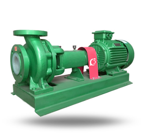
IHF Fluoroplastic Alloy Chemical Pump is a single-stage horizontal centrifugal pump with fluoroplastic-lined wetted parts, designed for highly corrosive chemical liquid transfer in industrial process systems.
It resolves severe corrosion failure, short service life of metal pumps, and leakage risks in aggressive acid-alkali media.
It is suitable for acid and alkali transfer, pickling systems, electroplating circulation, chemical dosing, and aggressive liquid process transport.
Model Designation

Applications
Typical Operating Scenarios
- Concentrated sulfuric acid transfer lines
- Hydrochloric acid pickling circulation systems
- Electroplating chemical circulation
- Alkali solution dosing and transfer
- Chlor-alkali process liquid handling
- Corrosive wastewater transfer in chemical plants
Engineering Advantages 关键工程优势
Structural Design Logic & Engineering Results
• Fluoroplastic alloy lining provides superior corrosion resistance against strong acids and alkalis → Extended service life in aggressive media
• Back pull-out structure enables maintenance without dismantling pipeline → Reduced downtime
• Heavy-duty shaft support with corrosion-resistant sleeve → Improved mechanical stability
• Standardized mechanical seal chamber design → Compatible with multiple sealing configurations
System Components
IHF Fluoroplastic Alloy Chemical Pump:
- Pump casing (fluoroplastic lined)
- Closed impeller (fluoroplastic alloy)
- Pump shaft with corrosion-resistant sleeve
- Mechanical seal assembly
- Bearing housing
- Base frame
Technical Specifications
Service Conditions
Suitable for highly corrosive acids, alkalis, oxidizing agents, and organic solvents without solid particles.
Operating Conditions
- Flow Rate: 1.75 – 130 m³/h
- Head: 3.5 – 87 m
- Power Range: 0.75 – 45 kW
- Speed: 1450 / 2900 rpm
- Liquid Temperature: -20°C – 120°C
- Working Pressure: ≤ 1.6 MPa
Detailed parameter tables are provided below.
Installation & Dimensions
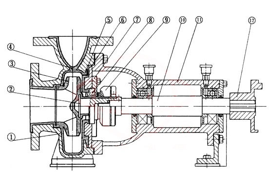
Outline Drawing
Performance Data
| No. | Name | No. | Name |
| 1 | Pump Body | 7 | Mechanical Seal Gland |
| 2 | Impeller Frame | 8 | Stationary Ring |
| 3 | Impeller | 9 | Rotary Ring |
| 4 | Pump Body Lining | 10 | Pump Shaft |
| 5 | Pump Cover Lining | 11 | Bearing Housing |
| 6 | Pump Cover | 12 | Coupling |
Performance Parameters
| Model | Speed | Flow Rate Q | Head | Efficiency | Power | Required NPSH | ||
| Shaft Power | Motor Power | |||||||
| r/min | m3/h | L/s | m | % | KW | KW | m | |
| IHF32-25-125 | 2900 |
3.5
5 6.5 |
0.97
1.39 1.8 |
21
20 18 |
40
44 42 |
0.5
0.62 0.76 |
1.5 | 2.3 |
| IHF32-25-125A | 2900 |
3.1
4.5 5.8 |
0.06
1.25 1.61 |
17.6
16 14.4 |
38
41 40 |
0.7
0.48 0.57 |
1.1 | 2.3 |
| IHF32-25-160 | 2900 |
3.5
5 6.5 |
0.97
1.39 1.8 |
33
32 30 |
34
40 42 |
0.93
1.1 1.26 |
2.2 | 2.3 |
| IHF32-25-160A | 2900 |
3.1
4.5 5.8 |
0.86
1.25 1.61 |
29
28 26 |
30
35 36 |
0.81
0.97 1.14 |
1.5 | 2.3 |
| IHF40-32-125 | 2900 |
4.4
6.5 8.3 |
1.22
1.8 2.31 |
21
20 18 |
40
45 43 |
0.63
0.79 0.95 |
2.2 | 2.5 |
| IHF40-32-125A | 2900 |
3.9
5.6 7.4 |
1.08
1.56 2.06 |
17.6
16 14.4 |
38
42 40 |
0.49
0.58 0.72 |
1.5 | 2.5 |
| IHF40-32-160 | 2900 |
4.4
6.5 8.3 |
1.22
1.8 2.31 |
33
32 30 |
34
40 39 |
1.16
1.42 1.71 |
2.2 | 2.5 |
| IHF40-32-160A | 2900 |
3.9
5.6 7.4 |
1.08
1.56 2.06 |
29
28 26 |
32
38 37 |
0.96
1.23 1.41 |
1.5 | 2.5 |
| Model | Speed | Flow Rate Q | Head | Efficiency | Power | Required NPSH | ||
| Shaft Power | Motor Power | |||||||
| r/min | m3/h | L/s | m | % | KW | KW | m | |
| IHF50-32-125 | 2900 |
8.8
12.5 16.3 |
2.44
3.47 4.53 |
21.5
20 17.5 |
45
54 53 |
1.15
1.26 1.47 |
2.2 | 3.0 |
| IHF50-32-125A | 2900 |
8
11 14.5 |
2.22
3.05 4.03 |
17
16 14 |
42
52 51 |
0.88
0.92 1.08 |
1.5 | 3.0 |
| IHF50-32-160 | 2900 |
8.8
12.5 16.3 |
1.08
1.56 2.06 |
33
32 30 |
41
48 47 |
1.93
2.27 2.84 |
4 | 3.0 |
| IHF50-32-160A | 2900 |
8.2
11.7 15.2 |
2.28
3.25 4.22 |
29
28 26 |
39
47 46 |
1.16
1.88 2.34 |
3 | 3.0 |
| IHF50-32-200 | 2900 |
8.8
12.5 16.3 |
2.44
3.47 4.53 |
52
50 48 |
34
42 41 |
3.7
4.1 5.2 |
7.5 | 3.0 |
| IHF50-32-200A | 2900 |
8.2
11.7 15.2 |
2.28
3.25 4.22 |
45
44 42 |
31
40 39 |
3.24
3.5 4.45 |
5.5 | 3.0 |
| IHF50-32-250 | 2900 |
8.8
12.5 16.3 |
1.08
1.56 2.06 |
82
80 76 |
27
35 34 |
7.3
7.8 10 |
11 | 3.0 |
| IHF50-32-250A | 2900 |
8.2
11.7 15.2 |
2.28
3.25 4.22 |
71
70 68 |
25
34 33 |
4.53
6.56 8.52 |
7.5 | 3.0 |
| Model | Speed | Flow Rate Q | Head | Efficiency | Power | Required NPSH | ||
| Shaft Power | Motor Power | |||||||
| r/min | m3/h | L/s | m | % | KW | KW | m | |
| IHF65-50-125 | 2900 |
17.5
25 32 |
4.86
6.94 8.89 |
21.5
20 17.5 |
56
64 63 |
1.83
2.13 2.42 |
3 | 3.5 |
| IHF65-50-125A | 2900 |
15.6
22.3 29 |
4.33
6.19 8.06 |
17
16 14 |
53
62 61 |
1.36
1.57 1.79 |
2.2 | 3.5 |
| IHF65-50-160 | 2900 |
17.5
25 32 |
4.86
6.94 8.89 |
33
32 27.5 |
50
59 57 |
3.15
3.69 4.2 |
5.5 | 3.5 |
| IHF65-50-160A | 2900 |
16.4
23.3 30.4 |
4.56
6.47 8.44 |
29
28 24 |
48
58 56 |
2.7
3.1 3.54 |
4 | 3.5 |
| IHF65-40-200 | 2900 |
17.5
25 32 |
4.86
6.94 8.89 |
52
50 45.5 |
45
54 54 |
5.5
6.3 7.35 |
11 | 3.5 |
| IHF65-40-200A | 2900 |
16.4
23.3 30.4 |
4.56
6.47 8.44 |
46
44 40 |
43
53 52 |
4.3
5 5.2 |
7.5 | 3.5 |
| IHF65-40-250 | 2900 |
17.5
25 32 |
4.86
6.94 8.89 |
82
80 76 |
39
50 52 |
10.1
10.9 12.74 |
18.5 | 3.5 |
| IHF65-40-250A | 2900 |
16.4
23.3 30.4 |
4.56
6.47 8.44 |
71
70 68 |
36
48 50 |
8.8
9.3 11.25 |
15 | 3.5 |
| Model | Speed | Flow Rate Q | Head | Efficiency | Power | Required NPSH | ||
| Shaft Power | Motor Power | |||||||
| r/min | m3/h | L/s | m | % | KW | KW | m | |
| IHF80-65-125 | 2900 |
35
50 65 |
9.72
13.89 18.06 |
21.5
20 17 |
64
69 67 |
3.2
3.95 4.5 |
5.5 | 4.0 |
| IHF80-65-125A | 2900 |
31
45 58 |
31
45 58 |
17
16 14 |
62
68 67 |
2.3
2.88 3.3 |
4 | 4.0 |
| IHF80-65-160 | 2900 |
35
50 65 |
9.72
13.89 18.06 |
33
32 27.5 |
60
68 67 |
5.24
6.41 7.27 |
11 | 4.0 |
| IHF80-65-160A | 2900 |
31
45 58 |
31
45 58 |
29
28 24 |
58
67 66 |
4.3
5 5.2 |
7.5 | 4.0 |
| IHF80-50-200 | 2900 |
35
50 65 |
9.72
13.89 18.06 |
52
50 48 |
52
64 65 |
9.53
10.64 12.39 |
15 | 4.0 |
| IHF80-50-200A | 2900 |
31
45 58 |
31
45 58 |
46
44 40 |
50
63 62 |
7.35
8.56 10 |
11 | 4.0 |
| IHF80-50-250 | 2900 |
35
50 65 |
9.72
13.89 18.06 |
82
80 72 |
40
50 51 |
19.4
21.8 25 |
30 | 4.0 |
| IHF80-50-250A | 2900 |
31
45 58 |
31
45 58 |
71.5
70 63 |
39
50 51 |
15.4
17.6 19.9 |
22 | 4.0 |
| Model | Speed | Flow Rate Q | Head | Efficiency | Power | Required NPSH | ||
| Shaft Power | Motor Power | |||||||
| r/min | m3/h | L/s | m | % | KW | KW | m | |
| IHF100-80-125 | 2900 |
70
100 130 |
19.4
27.8 36.1 |
23
20 14 |
70
75 65 |
6.26
7.26 7.63 |
11 | 5.0 |
| IHF100-80-125A | 2900 |
62.6
89 116 |
17.4
24.7 32.2 |
18
16 11 |
68
73 65 |
4.5
5.3 5.74 |
7.5 | 5.0 |
| IHF100-80-160 | 2900 |
70
100 130 |
19.4
27.8 36.1 |
33
32 27.5 |
68
74 65 |
9.53
11.78 13.03 |
15 | 5.0 |
| IHF100-80-160A | 2900 |
65.4
93.5 121 |
18.2
26 33.6 |
32
28 21 |
66
73 65 |
8.6
9.3 10.6 |
11 | 5.0 |
| IHF100-65-200 | 2900 |
70
100 130 |
19.4
27.8 36.1 |
52
50 48 |
64
72 71 |
15.5
18.91 20.94 |
30 | 5.0 |
| IHF100-65-200A | 2900 |
65.4
93.5 121 |
18.2
26 33.6 |
46
44 40 |
63
71 70 |
13
15.02 17.4 |
22 | 5.0 |
| IHF100-65-250 | 2900 |
70
100 130 |
19.4
27.8 36.1 |
87
80 68 |
62
69 68 |
26.6
31.6 35 |
45 | 4.0 |
| IHF100-65-250A | 2900 |
65.4
93.5 121 |
18.2
26 33.6 |
76.5
70 59 |
60
68 67 |
20.25
26.2 28 |
37 | 4.5 |
| Model | Speed | Flow Rate Q | Head | Efficiency | Power | Required NPSH | ||
| Shaft Power | Motor Power | |||||||
| r/min | m3/h | L/s | m | % | KW | KW | m | |
| IHF32-25-125 | 1450 |
1.75
2.5 3.25 |
0.49
0.69 0.9 |
5.25
5 4.5 |
37
40 38 |
0.068
0.085 0.105 |
0.75 | 2.3 |
| IHF32-25-160 | 1450 |
1.75
2.5 3.25 |
0.49
0.69 0.9 |
8.25
8 7.5 |
30
38 40 |
0.131
0.143 0.166 |
0.75 | 2.3 |
| IHF40-32-125 | 1450 |
2.2
3.25 4.15 |
0.6
0.9 1.15 |
5.25
5 4.5 |
37
41 40 |
0.085
0.108 0.127 |
0.75 | 2.5 |
| IHF40-32-160 | 1450 |
2.2
2.5 3.25 |
0.6
0.9 1.15 |
8.25
8 7.5 |
33
36 37 |
0.14
0.15 0.18 |
0.75 | 2.5 |
| Model | Speed | Flow Rate Q | Head | Efficiency | Power | Required NPSH | ||
| Shaft Power | Motor Power | |||||||
| r/min | m3/h | L/s | m | % | KW | KW | m | |
| IHF50-32-125 | 1450 |
4.4
6.25 8.15 |
1.2
1.74 2.26 |
5.37
5 4.37 |
37
46 45 |
0.17
0.18 |
0.75 | 3.0 |
| IHF50-32-160 | 1450 |
4.4
6.25 8.15 |
1.2
1.74 2.26 |
8.25
8 7.5 |
31
41 42 |
0.31
0.33 0.39 |
0.75 | 3.0 |
| IHF50-32-200 | 1450 |
4.4
6.25 8.15 |
1.2
1.74 2.26 |
13
12.5 12 |
25
33 36 |
0.62
0.65 0.74 |
1.5 | 3.0 |
| IHF50-32-250 | 1450 |
4.4
6.25 8.15 |
1.2
1.74 2.26 |
20.5
20 19 |
20
27 30 |
1.22
1.26 1.4 |
2.2 | 3.0 |
| IHF65-50-125 | 1450 |
17.5
25 32 |
4.86
6.94 8.89 |
5.37
5 4.37 |
45
57 58 |
0.28
0.3 0.33 |
0.75 | 3.5 |
| IHF65-50-160 | 1450 |
17.5
25 32 |
4.86
6.94 8.89 |
8.25
8 6.87 |
40
53 51 |
0.49
0.51 0.59 |
1.1 | 3.5 |
| IHF65-40-200 | 1450 |
17.5
25 32 |
4.86
6.94 8.89 |
13
12.5 11.4 |
36
46 47 |
0.86
0.93 1.05 |
1.5 | 3.5 |
| IHF65-40-250 | 1450 |
17.5
25 32 |
4.86
6.94 8.89 |
20.5
20 19 |
32
42 44 |
1.52
1.62 1.88 |
3 | 3.5 |
| Model | Speed | Flow Rate Q | Head | Efficiency | Power | Required NPSH | ||
| Shaft Power | Motor Power | |||||||
| r/min | m3/h | L/s | m | % | KW | KW | m | |
| IHF80-65-125 | 1450 |
17.5
25 32 |
4.86
6.94 8.89 |
5.37
5 4.25 |
54
64 62 |
0.47
0.53 0.61 |
1.1 | 4.0 |
| IHF80-65-160 | 1450 |
17.5
25 32 |
4.86
6.94 8.89 |
8.25
8 7.5 |
50
62 61 |
0.78
0.88 1 |
1.5 | 4.0 |
| IHF80-50-200 | 1450 |
17.5
25 32 |
4.86
6.94 8.89 |
13
12.5 11.38 |
51
59 58 |
1.21
1.44 1.74 |
3 | 4.0 |
| IHF80-50-250 | 1450 |
17.5
25 32 |
4.86
6.94 8.89 |
20.5
20 18 |
40
50 51 |
2.4
2.7 3.12 |
4 | 4.0 |
| IHF100-80-125 | 1450 |
35
50 65 |
9.72
13.89 18.06 |
5.75
5 3.5 |
65
70 64 |
0.85
0.97 0.98 |
1.5 | 4.5 |
| IHF100-80-160 | 1450 |
35
50 65 |
9.72
13.89 18.06 |
8.5
8 6.5 |
60
68 67 |
1.35
1.6 1.69 |
2.2 | 4.5 |
| IHF100-65-200 | 1450 |
35
50 65 |
9.72
13.89 18.06 |
13
12.5 10.5 |
60
68 63 |
2.06
2.5 2.95 |
4 | 4.5 |
| IHF100-65-250 | 1450 |
35
50 65 |
9.72
13.89 18.06 |
21.2
20 18.5 |
58
63 62 |
3
4.3 4.72 |
5.5 | 4.5 |
How to Select a Pump Model
IHF Chemical Pump Selection Criteria
- Confirm chemical compatibility between fluoroplastic lining and media composition.
- Determine required duty point (flow rate & head) within high-efficiency range.
- Evaluate sealing requirements based on toxicity and volatility.
- Confirm temperature and pressure limits of system pipeline.
- Consider NPSH conditions to prevent cavitation under corrosive service.
✔ Final model configuration should be determined based on chemical compatibility, duty point, and sealing requirements.
Engineering Notes
- Not suitable for slurry or media containing abrasive solids.
- Avoid dry-running to protect fluoroplastic lining.
- Thermal expansion of fluoroplastic must be considered in high-temperature applications.
- Mechanical seal flushing plan may be required for volatile chemicals.
Compliance & Quality Assurance
- Factory hydrostatic pressure test
- Hydraulic performance curve verification
- Fluoroplastic lining thickness inspection
- Shaft dynamic balance test
- Optional third-party inspection available
Safety Notice
- Do not operate under dry-running condition
- Ensure proper priming before startup
- Avoid operation beyond rated pressure
- Disconnect power before maintenance
OEM & Customization
This pump series supports engineered configuration and duty-based matching. Technical adjustments can be made according to system requirements and installation conditions.
Available options include:
• Motor voltage & frequency
• Mechanical seal type and configuration
• Wetted parts material selection
• Surface coating and corrosion protection
Configuration is determined based on duty point and project specifications.
FAQs
Q1: Can the IHF pump operate under VFD control?
Yes, operation under variable frequency control is acceptable within rated speed range.
Q2: What sealing options are available?
Single mechanical seal, double mechanical seal, and cartridge seal configurations are available.
Q3: What is the allowable working pressure?
Maximum allowable working pressure is ≤ 1.6 MPa.
Q4: What media are compatible with fluoroplastic lining?
Strong acids, alkalis, oxidizing agents, and most corrosive chemicals without solids.
Q5: Is the pump suitable for high-temperature chemicals?
Operating temperature range is -20°C to 120°C.
Q6: Does the pump require external flushing?
For volatile or hazardous chemicals, external seal flushing may be recommended.