Article Content
ISG Vertical Pipeline Centrifugal Pump
Complete Technical Specifications & Performance Analysis Guide
Executive Summary
The ISG series vertical pipeline centrifugal pumps represent optimized hydraulic engineering for inline installation in water supply, HVAC, and industrial circulation systems. This comprehensive technical specification document provides engineers with detailed performance data, dimensional information, material specifications, and selection criteria essential for proper pump specification and system design. The inline design with suction and discharge flanges on the same centerline eliminates space-consuming piping elbows while maintaining high efficiency up to 85% and reliable long-term operation. Understanding complete technical specifications enables optimal pump selection achieving best efficiency point operation and minimizing lifecycle costs.
1. Design Philosophy and Engineering Principles
1.1 Hydraulic Design Optimization
ISG pumps employ advanced hydraulic modeling using computational fluid dynamics (CFD) to optimize impeller and volute geometry. The design objectives include: maximizing efficiency across operating range, minimizing NPSH requirements, ensuring stable head-flow curve without dip, and reducing hydraulic noise. Three-dimensional impeller profiles with carefully controlled blade angles achieve smooth flow transition and minimize turbulence losses.
1.2 Mechanical Design Features
Vertical inline configuration provides significant installation advantages: direct pipeline mounting without space-consuming elbows, reduced foundation requirements, simplified alignment, and compact footprint suitable for space-constrained mechanical rooms. The rigid shaft design with oversized shaft diameter minimizes deflection ensuring optimal mechanical seal performance and extended bearing life.

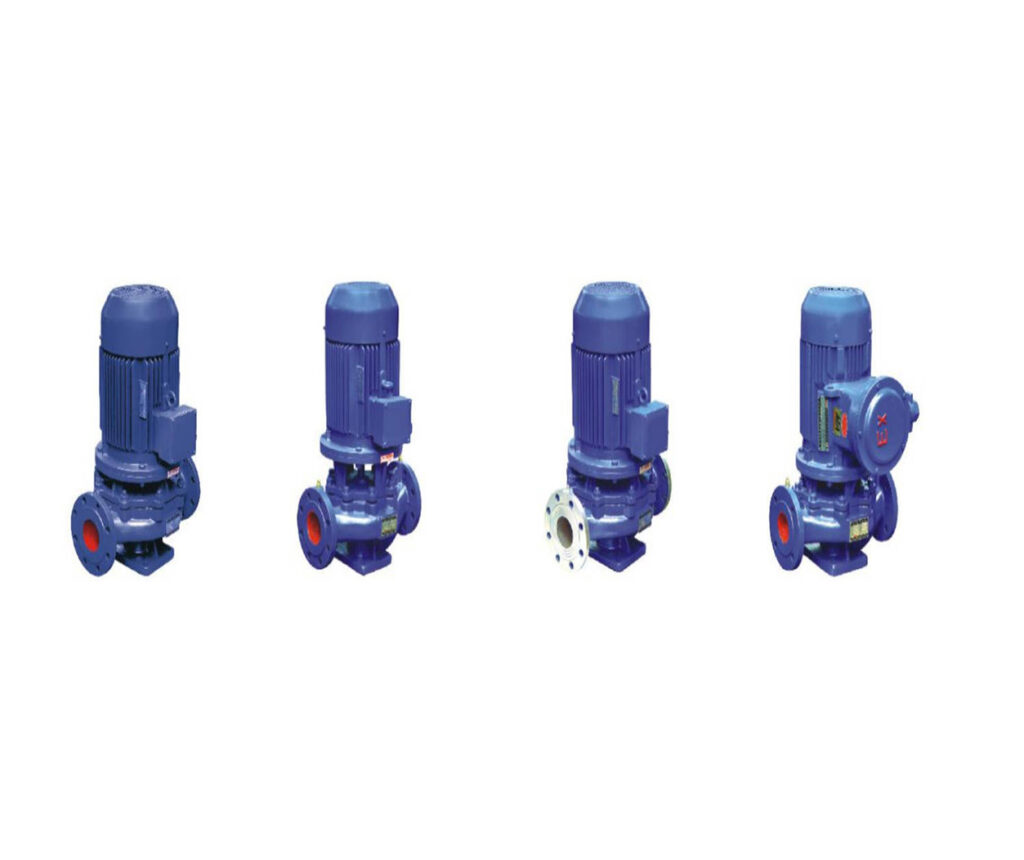
Figure 1: ISG Series Vertical Pipeline Pump – Inline Design with Suction and Discharge on Same Centerline
2. Complete Performance Specifications
2.1 Operating Envelope
| Parameter | Range | Unit | Notes |
|---|---|---|---|
| Flow Rate | 1.5 – 1600 | m³/h | Based on model selection |
| Total Head | 5 – 150 | m | Single stage design |
| Rotational Speed | 1450 / 2900 | r/min | 4-pole / 2-pole motor |
| Motor Power | 0.37 – 250 | kW | Matched to duty point |
| Overall Efficiency | Up to 85 | % | Peak at BEP |
| NPSH Required | 2.0 – 5.0 | m | At rated flow |
| Liquid Temperature | -10 to +80 | °C | Standard ISG type |
| Max Working Pressure | 1.6 | MPa | 16 bar rating |
2.2 Performance Curve Characteristics
The head-flow curve exhibits continuous downward slope from shut-off to run-out ensuring stable operation without instability or hump. Shut-off head typically equals 110-130% of head at best efficiency point. The power curve rises continuously with flow – important for motor sizing to prevent overload at run-out conditions.
2.3 Efficiency Analysis
Peak efficiency occurs at best efficiency point (BEP) where hydraulic losses are minimized. High efficiency zone extends from 70% to 120% of BEP flow providing operational flexibility. Preferred Operating Region (POR) per Hydraulic Institute standards is 70-120% BEP where vibration remains acceptable and bearing life is maximized. Allowable Operating Region (AOR) may extend from 50-130% BEP with reduced reliability.
3. Model Designation and Selection
3.1 Naming Convention
Example: ISG 80-160
- ISG: Vertical pipeline centrifugal pump
- 80: Nominal inlet diameter in millimeters
- 160: Impeller nominal diameter in millimeters
3.2 Variant Designations
| Model Code | Configuration | Temperature Range | Application |
|---|---|---|---|
| ISG | Standard cast iron | -10°C to +80°C | Clean water supply |
| IRG | Hot water version | -10°C to +120°C | Heating systems |
| IHG | Chemical grade | -20°C to +120°C | Corrosive liquids |
| GRG | High temperature | -20°C to +240°C | Thermal oil systems |
| YG | Oil duty | -20°C to +120°C | Petroleum products |
4. Detailed Model Performance Data
4.1 Small Flow Models (ISG25-ISG40)
| Model | Flow | Head | Power | Speed | Eff. | NPSHr | Weight |
|---|---|---|---|---|---|---|---|
| ISG25-125A | 3.2 m³/h | 16 m | 0.75 kW | 2900 | 54% | 2.0 m | 25 kg |
| ISG25-160 | 3.2 m³/h | 28 m | 1.1 kW | 2900 | 52% | 2.0 m | 28 kg |
| ISG32-125 | 5.0 m³/h | 20 m | 0.75 kW | 2900 | 58% | 2.0 m | 27 kg |
| ISG40-125 | 6.3 m³/h | 20 m | 1.1 kW | 2900 | 60% | 2.0 m | 30 kg |
| ISG40-160 | 6.3 m³/h | 32 m | 1.5 kW | 2900 | 60% | 2.2 m | 35 kg |
4.2 Medium Flow Models (ISG50-ISG80)
| Model | Flow | Head | Power | Speed | Eff. | Weight |
|---|---|---|---|---|---|---|
| ISG50-125 | 12.5 m³/h | 20 m | 1.5 kW | 2900 | 63% | 35 kg |
| ISG50-160 | 12.5 m³/h | 32 m | 2.2 kW | 2900 | 62% | 40 kg |
| ISG50-200 | 12.5 m³/h | 50 m | 3.0 kW | 2900 | 66% | 45 kg |
| ISG65-125 | 25.0 m³/h | 20 m | 2.2 kW | 2900 | 67% | 42 kg |
| ISG65-160 | 25.0 m³/h | 32 m | 4.0 kW | 2900 | 68% | 48 kg |
| ISG80-125 | 50.0 m³/h | 20 m | 4.0 kW | 2900 | 70% | 55 kg |
| ISG80-160 | 50.0 m³/h | 32 m | 7.5 kW | 2900 | 70% | 65 kg |
4.3 Large Flow Models (ISG100-ISG150)
| Model | Flow | Head | Power | Speed | Eff. | Weight |
|---|---|---|---|---|---|---|
| ISG100-125 | 100 m³/h | 20 m | 7.5 kW | 2900 | 72% | 85 kg |
| ISG100-160 | 100 m³/h | 32 m | 15 kW | 2900 | 74% | 100 kg |
| ISG100-200 | 100 m³/h | 50 m | 18.5 kW | 2900 | 72% | 120 kg |
| ISG125-125 | 160 m³/h | 20 m | 11 kW | 2900 | 75% | 110 kg |
| ISG125-160 | 160 m³/h | 32 m | 22 kW | 2900 | 76% | 135 kg |
| ISG150-200 | 200 m³/h | 50 m | 45 kW | 1450 | 78% | 250 kg |

Figure 2: ISG Series Performance Curves – Head, Efficiency, and Power vs Flow Rate
5. Construction Materials Specification
5.1 Standard Configuration (ISG)
| Component | Material | Standard | Properties |
|---|---|---|---|
| Pump Casing | Gray Cast Iron | HT200 / GG25 | Good castability, damping |
| Impeller | Gray Cast Iron | HT200 | Hydraulically smooth |
| Pump Shaft | Carbon Steel | 45# / AISI 1045 | High strength, hardened |
| Wear Rings | Brass | HPb59-1 | Low friction, wear resistant |
| Mechanical Seal | Carbon/SiC | Standard | Long life, low leakage |
| Bearings | Deep Groove Ball | SKF/NSK | Premium quality |
5.2 Optional Material Upgrades
| Application | Material Upgrade | Benefit |
|---|---|---|
| Corrosive liquids | Stainless Steel 304 | Enhanced corrosion resistance |
| Food grade | Stainless Steel 316L | Sanitary, easy clean |
| High wear | Ductile Iron / Bronze | Improved wear resistance |
| Sea water | Duplex Stainless | Chloride resistance |
6. Operating Limits and Constraints
6.1 Temperature Limits
| Model Variant | Min Temp | Max Temp | Special Requirements |
|---|---|---|---|
| ISG Standard | -10°C | +80°C | Standard seal |
| IRG Hot Water | -10°C | +120°C | High temp seal |
| IHG Chemical | -20°C | +120°C | Chemical seal |
| GRG High Temp | -20°C | +240°C | Cooling system |
6.2 Pressure Ratings
Maximum Working Pressure: 1.6 MPa (16 bar) – sum of suction pressure plus pump head must not exceed this limit.
Maximum Suction Pressure: 0.6 MPa (6 bar) – higher suction pressure requires consultation.
Hydrostatic Test Pressure: 2.4 MPa (24 bar) – factory test pressure per ISO requirements.
6.3 Liquid Properties
- pH Range: 6-9 standard construction, 2-13 with stainless steel
- Viscosity: Maximum 5 cSt for standard impellers
- Solids Content: Clean liquids only – no suspended solids
- Density: Maximum 1200 kg/m³ – higher density requires power correction
7. Electrical Specifications
7.1 Motor Data
| Parameter | Specification | Standard |
|---|---|---|
| Voltage | 380V ±10%, 50Hz, 3-phase | IEC 60034 |
| Alternative Voltages | 220V, 415V, 460V | Optional |
| Insulation Class | Class F (155°C) | IEC 60085 |
| Protection Class | IP55 | IEC 60529 |
| Duty Rating | S1 Continuous | IEC 60034-1 |
| Efficiency Class | IE2 Standard, IE3 Optional | IEC 60034-30 |
7.2 Starting Methods
- Direct-On-Line (DOL): Standard for motors ≤7.5kW
- Star-Delta: Recommended for motors 7.5-37kW
- Soft Starter: Optional for reduced mechanical stress
- VFD: Optional for flow control and energy saving
8. Dimensional Data
8.1 Connection Flanges
| Size Range | DN | PN | Standard | Drilling |
|---|---|---|---|---|
| Small | 25-50 | 16 | GB/T 9119 | 4 bolt holes |
| Medium | 65-100 | 16 | GB/T 9119 | 8 bolt holes |
| Large | 125-150 | 16 | GB/T 9119 | 8 bolt holes |
9. Selection Methodology
9.1 System Curve Calculation
Total head required equals static head plus friction losses. Static head is elevation difference plus pressure differential. Friction losses calculated using Darcy-Weisbach equation accounting for pipe length, diameter, roughness, and fittings. Add 10% safety margin to calculated head.
9.2 NPSH Analysis
NPSH available must exceed NPSH required by minimum 0.5m margin. NPSHa calculation: atmospheric pressure head plus static suction head minus friction losses minus vapor pressure. Low NPSHa causes cavitation damaging impellers and reducing performance.
10. Technical Support
Shanghai Chaodun Machinery Manufacturing Group Co., Ltd. provides comprehensive technical support including pump selection, submittal preparation, and application engineering.
Website: https://cd-pump.com