Product Overview
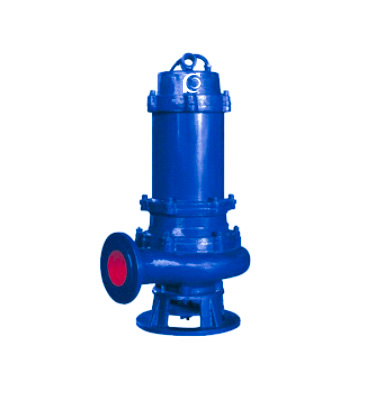
The JYWQ, JBWQ, and JPWQ Series Automatic Mixing Sewage Pumps are designed with an integrated automatic mixing mechanism, developed for wastewater pumping applications. The mixing mechanism rotates synchronously with the motor shaft, continuously agitating the settled sludge at the bottom of the water tank and suspending solid materials in the liquid, which are then pumped out. This design significantly improves resistance to sedimentation, reduces clogging risks, and enhances overall discharge stability.
The JYWQ and JBWQ models are equipped with standard configurations, while the JPWQ model features a stainless steel outer sleeve and an internal circulation cooling system, designed to handle more demanding operational conditions.
Model Designation

Key Features
-
Automatic mixing mechanism that continuously agitates settled sludge, effectively preventing sediment accumulation and reducing cleaning requirements;
-
Impeller design provides cutting and shredding capabilities for solids and long fibers, enhancing solid handling performance;
-
Mechanical seals with advanced hard alloy friction pairs, operating in an oil chamber, improving sealing reliability for long-term stability;
-
Compact design with a small footprint, low noise, and easy maintenance and part replacement;
-
Optional automatic control system, enabling automatic start/stop based on liquid level changes, reducing manual intervention;
-
Multiple installation options available, allowing installation and maintenance without entering the sewage pit;
-
Outdoor-rated motor configuration allows the pump to be directly installed outdoors without the need for a pump room, reducing overall installation and construction costs.
Engineering Summary
The JYWQ, JBWQ, and JPWQ Series Sewage Pumps adopt an integrated “mixing + pumping” design, allowing for simultaneous drainage, sludge agitation, and decontamination in a single operating cycle. This significantly reduces manual cleaning requirements and lowers overall system operation costs. The pumps are designed with efficient hydraulic performance and robust materials, ensuring long-term, reliable operation in high-solid content sewage applications. The JPWQ model, with its stainless steel outer sleeve and internal cooling system, is designed for more challenging operating conditions.
Typical Applications
The JYWQ, JBWQ, and JPWQ Series Automatic Mixing Sewage Pumps are suitable for:
-
Industrial and commercial wastewater discharge systems
-
Municipal sewage treatment plants
-
Hospitals and hotels wastewater systems
-
Residential sewage pumping stations
-
Civil defense and emergency drainage systems
-
Municipal engineering projects and construction site drainage
-
Auxiliary dewatering in mining operations
-
Rural biogas pits, agricultural irrigation, and similar applications
The pump is designed for handling sewage with solid particles and wastewater, and is also suitable for clean water or mildly corrosive fluids.
System & Operation
Components & Supply
-
Automatic mixing mechanism, effectively preventing sediment accumulation and reducing manual cleaning needs;
-
Cutting impeller design, enhancing the ability to handle solids and long fibers, reducing clogging risks;
-
Abrasion-resistant mechanical seals, ensuring long-term stable operation in an oil chamber;
-
Compact design, small footprint, low noise, and easy maintenance, enabling quick component replacement;
-
Optional fully automatic control panel for start/stop operation based on liquid level changes, reducing manual intervention.
Technical Specifications
Operating Conditions
-
Liquid Temperature:
• Standard Pump: ≤ 40°C
• Hot Water Pump: ≤ 80°C (special applications can meet up to 120°C) -
Ambient Temperature: ≤ +40°C
-
Maximum Working Pressure: 10 bar
-
Maximum Allowable Inlet Pressure: Limited by system working pressure
-
Fluid Requirements:
• Clean, low-viscosity, non-flammable, sulfur-free liquids, free from solid particles or fibers
• Suitable for pumping mineral water, softened water, purified water, light oils, and mild chemical fluids
• If the liquid’s density or viscosity exceeds that of water, a higher-rated motor should be selected
• The pump’s suitability for specific liquids depends on factors such as chloride content, pH, temperature, and solvent/oil content
Service Conditions
-
Installation Altitude: Must not exceed 1000 meters; for higher elevation applications, specify at the time of order for proper configuration.
-
The pump must not be used in flammable or explosive environments, nor should it handle combustible liquids.
-
Installation should be in a well-ventilated, dry, and vibration-free location.
-
Maximum ambient temperature should not exceed +40°C.
Protection Functions
-
The motor should be equipped with overload protection, phase failure protection, and overheat protection devices to prevent damage under abnormal conditions.
-
Dry-run protection is recommended to prevent mechanical seal failure in case of insufficient water supply.
-
Pressure switches or variable frequency drives (VFDs) should be used to maintain safe pressure ranges.
-
Check valves and anti-backflow devices must be installed to prevent damage caused by reverse flow after shutdown.
Selection Criteria
-
Select the pump model and number of stages based on required flow rate and head.
-
Choose appropriate wetted materials (e.g., SS304, SS316L) based on fluid temperature, pH, and chloride content.
-
Select sealing structure (mechanical seal or packing seal) based on the fluid’s corrosive properties.
-
Ensure installation space and piping layout compatibility with the horizontal configuration.
-
If the pumped liquid has higher viscosity or density than water, a higher-rated motor should be selected to meet the required shaft power.
Installation & Dimensions
Outline Drawing

Performance Data
|
No.
|
Name
|
|
1
|
Main Cable
|
|
2
|
Motor Housing
|
|
3
|
Internal Circulation Sleeve
|
|
4
|
Oil Chamber
|
|
5
|
Auxiliary Impeller
|
|
6
|
Impeller
|
|
7
|
Pump Body
|
|
8
|
Base
|
|
9
|
Partition Plate
|
|
10
|
Control Cable
|
|
11
|
Oil-Water Probe
|
|
12
|
Mechanical Seal
|
|
13
|
Agitator
|
Performance Parameters
|
Item No.
|
Model
|
Discharge Diameter |
Rated Flow Rate
|
Rated Head
|
Impeller Diameter
|
Speed (rpm)
|
Efficiency (%)
|
Auto-Coupling Device |
|
(mm)
|
(m3/h)
|
(mm)
|
(mm)
|
(r/min)
|
(%)
|
|||
|
1
|
JYWQ50-12-15-1200-1.5
|
50
|
12
|
15
|
1200
|
2900
|
48
|
CAK-50
|
|
2
|
JYWQ50-20-7-1200-1.1
|
50
|
20
|
7
|
1200
|
2900
|
62
|
CAK-50
|
|
3
|
JYWQ50-10-10-1200-1.1
|
50
|
10
|
10
|
1200
|
2900
|
56
|
CAK-50
|
|
4
|
JYWQ50-15-15-1200-2.2
|
50
|
15
|
15
|
1200
|
2900
|
51
|
CAK-50
|
|
5
|
JYWQ50-25-10-1200-2.2
|
50
|
25
|
10
|
1200
|
2900
|
65
|
CAK-50
|
|
6
|
JYWQ50-15-20-1200-2.2
|
50
|
15
|
20
|
1200
|
2900
|
56
|
CAK-50
|
|
7
|
JYWQ50-20-15-1200-2.2
|
50
|
20
|
15
|
1200
|
2900
|
56
|
CAK-50
|
|
8
|
JYWQ50-42-9-1200-3
|
50
|
42
|
9
|
1200
|
2900
|
56
|
CAK-50
|
|
9
|
JYWQ50-17-25-1200-3
|
50
|
17
|
25
|
1200
|
2900
|
56
|
CAK-50
|
|
10
|
JYWQ50-25-22-1200-4
|
50
|
25
|
22
|
1200
|
2900
|
62
|
CAK-50
|
|
11
|
JYWQ50-40-15-1400-4
|
50
|
40
|
15
|
1400
|
2900
|
70
|
CAK-50
|
|
12
|
JYWQ50-25-32-1600-5.5
|
50
|
25
|
32
|
1600
|
2900
|
52
|
CAK-50
|
|
13
|
JYWQ50-40-30-1600-7.5
|
50
|
40
|
30
|
1600
|
2900
|
68
|
CAK-50
|
|
14
|
JYWQ65-25-15-1400-3
|
65
|
25
|
150
|
1400
|
2900
|
65
|
CAK-65
|
|
15
|
JYWQ65-37-13-1400-3
|
65
|
37
|
13
|
1400
|
2900
|
62
|
CAK-65
|
|
16
|
JYWQ65-25-28-1400-4
|
65
|
25
|
28
|
1400
|
2900
|
60
|
CAK-65
|
|
17
|
JYWQ80-40-7-1600-2.2
|
80
|
40
|
7
|
1600
|
2900
|
54
|
CAK-80
|
|
18
|
JYWQ80-29-8-1600-2.2
|
80
|
29
|
8
|
1600
|
2900
|
54
|
CAK-80
|
|
19
|
JYWQ80-43-13-1600-4
|
80
|
43
|
13
|
1600
|
2900
|
63
|
CAK-80
|
|
20
|
JYWQ80-50-10-1600-3
|
80
|
50
|
10
|
1600
|
1450
|
76
|
CAK-80
|
|
21
|
JYWQ80-40-15-1600-4
|
80
|
40
|
15
|
1600
|
2900
|
70
|
CAK-80
|
|
22
|
JYWQ80-60-13-1600-4
|
80
|
60
|
13
|
1600
|
2900
|
70
|
CAK-80
|
|
23
|
JYWQ80-35-25-1600-5.5
|
80
|
35
|
25
|
1600
|
2900
|
64
|
CAK-80
|
|
24
|
JYWQ80-50-25-1600-7.5
|
80
|
50
|
25
|
1600
|
2900
|
70
|
CAK-80
|
|
25
|
JYWQ80-50-30-1600-7.5
|
80
|
50
|
30
|
1600
|
2900
|
70
|
CAK-80
|
|
26
|
JYWQ100-80-9-2000-4
|
100
|
80
|
9
|
2000
|
1450
|
62
|
CAK-100
|
|
27
|
JYWQ100-110-10-2000-5.5
|
100
|
110
|
10
|
2000
|
1450
|
71
|
CAK-100
|
|
28
|
JYWQ100-70-15-2000-5.5
|
100
|
70
|
15
|
2000
|
1450
|
71
|
CAK-100
|
|
29
|
JYWQ100-100-15-2000-7.5
|
100
|
100
|
15
|
2000
|
1450
|
73
|
CAK-100
|
|
30
|
JYWQ100-80-20-2000-7.5
|
100
|
70
|
20
|
2000
|
2900
|
71
|
CAK-100
|
|
31
|
JYWQ100-50-35-2000-11
|
100
|
100
|
35
|
2000
|
2900
|
68
|
CAK-100
|
|
32
|
JYWQ100-70-22-2000-7.5
|
100
|
80
|
22
|
2000
|
2900
|
70
|
CAK-100
|
|
33
|
JYWQ100-100-22-2000-15
|
100
|
150
|
22
|
2000
|
1450
|
61
|
CAK-100
|
|
34
|
JYWQ100-80-30-2000-15
|
100
|
210
|
30
|
2000
|
1450
|
67
|
CAK-100
|
|
35
|
JYWQ150-150-10-2000-7.5
|
150
|
250
|
10
|
2000
|
1450
|
75
|
CAK-150
|
|
36
|
JYWQ150-210-7-2500-7.5
|
150
|
150
|
7
|
2500
|
1450
|
78
|
CAK-150
|
|
37
|
JYWQ150-250-6-2500-7.5
|
150
|
200
|
6
|
2500
|
1450
|
79
|
CAK-150
|
|
38
|
JYWQ150-150-15-2500-11
|
150
|
65
|
15
|
2500
|
1450
|
79
|
CAK-150
|
|
39
|
JYWQ150-200-10-2500-15
|
150
|
180
|
10
|
2500
|
1450
|
73
|
CAK-150
|
|
40
|
JYWQ150-65-40-3200-18.5
|
150
|
150
|
40
|
3200
|
1450
|
58
|
CAK-150
|
|
41
|
JYWQ150-180-22-2600-18.5
|
150
|
110
|
22
|
2600
|
1450
|
75
|
CAK-150
|
|
42
|
JYWQ150-150-26-2600-18.5
|
150
|
300
|
26
|
2600
|
1450
|
72
|
CAK-150
|
|
43
|
JYWQ150-110-30-2600-18.5
|
150
|
130
|
30
|
2600
|
1450
|
72
|
CAK-150
|
|
44
|
JYWQ150-300-15-2600-22
|
150
|
100
|
15
|
2600
|
1450
|
76
|
CAK-150
|
|
45
|
JYWQ150-130-30-2600-22
|
150
|
300
|
30
|
2600
|
1450
|
70
|
CAK-150
|
|
46
|
JYWQ150-100-40-3000-30
|
150
|
250
|
40
|
3000
|
1450
|
64
|
CAK-150
|
|
47
|
JYWQ200-300-7-3000-11
|
200
|
300
|
7
|
3000
|
1450
|
75
|
CAK-200
|
|
48
|
JYWQ200-250-11-3000-15
|
200
|
250
|
11
|
3000
|
1450
|
72
|
CAK-200
|
|
49
|
JYWQ200-300-10-3000-15
|
200
|
300
|
10
|
3000
|
1450
|
75
|
CAK-200
|
|
50
|
JYWQ200-250-15-3000-18.5
|
200
|
250
|
15
|
3000
|
1450
|
72
|
CAK-200
|
|
51
|
JYWQ200-400-10-3000-22
|
200
|
400
|
10
|
3000
|
1450
|
75
|
CAK-200
|
|
52
|
JYWQ200-200-20-3000-22
|
200
|
200
|
20
|
3000
|
1450
|
73
|
CAK-200
|
|
53
|
JYWQ200-250-22-3000-30
|
200
|
250
|
22
|
3000
|
1450
|
73
|
CAK-200
|
|
54
|
JYWQ250-600-7-3000-22
|
250
|
600
|
7
|
3000
|
1450
|
78
|
CAK-250
|
|
55
|
JYWQ250-600-9-3000-30
|
250
|
600
|
9
|
3000
|
1450
|
78
|
CAK-250
|
Operating Manual
Pre-Operation Check
(1) Before operation, use a megohmmeter to check the insulation resistance between the motor stator and ground. The resistance should not be less than 50 MΩ.
(2) Check the power cable for any damage, such as breaks or wear. If any damage is found, replace the cable immediately to prevent leakage. Ensure that the cable cross-section matches the required current specifications.
(3) If the voltage exceeds ±10% of the rated voltage, do not start the pump.
(4) For safety, the grounding wire in the four-core power cable must be securely grounded to prevent electric shock.
Precautions
(5) When the pump is submerged in water, it must be lifted vertically. It should not be placed horizontally or allowed to sink into sludge. After use, lift the pump, clean it, and store it in a dry place to prevent freezing.
(6) Do not use the power cable as a lifting rope.
(7) Check the rotor’s direction of rotation. When viewed from above, it should rotate clockwise.
(8) Outdoor switches or terminals should be protected from rain and moisture. Never touch the switch with wet hands or barefoot to avoid electric shock.
(9) Always disconnect the power supply before moving the pump. Avoid touching the water source during operation to prevent electrical accidents.
(10) The pump motor should not run in a single-phase condition. If a fuse blows, check the cause before continuing use. Never replace the fuse with a higher-rated one.
Maintenance & Inspection
(11) During operation, assign a dedicated operator for the pump. If abnormalities are detected, immediately stop the pump, investigate the cause, and resolve the issue (for pumps without automatic protection systems).
(12) After approximately 6 months of operation under normal working conditions, inspect the oil chamber seals. If the oil appears emulsified or contains water sediment, replace the mechanical oil and seals. Pumps operating in harsh conditions should be inspected more frequently.
(13) Users should select the appropriate flow rate and head based on actual operating conditions to ensure optimal performance. The parameters shown on the pump nameplate or in the manual indicate the recommended operating conditions. The pump can be operated within 0.7 to 1.2 times the rated flow range, but exceeding this range may cause the motor to overload.
OEM & Custom
FAQs
- Q: Can you match our required duty point and solids handling?
A: Yes. Select from JYWQ/JBWQ/JPWQ ranges and impeller options; provide flow/head, solids size, and medium details. - Q: What voltages and frequencies are available?
A: 50/60 Hz, common voltages (220/380/400/415/460 V). Custom on request. - Q: Do you offer guide rail auto-coupling systems?
A: Yes, CAK-50 to CAK-250 for fast installation and maintenance. - Q: How do you ensure sealing reliability?
A: Dual mechanical seals in oil chamber, hydrodynamic auxiliary seal, leak/thermal protection options. - Q: Can the pump run at low water level?
A: JPWQ with internal circulation cooling is designed for low water-level operation. - Q: What certifications and tests can you provide?
A: Routine performance and pressure tests; export compliance documents and inspection reports are available. - Q: What information is needed for a quotation?
A: Medium, temperature, pH, flow/head duty point, site voltage/frequency, solids size, installation method, and accessories needed.