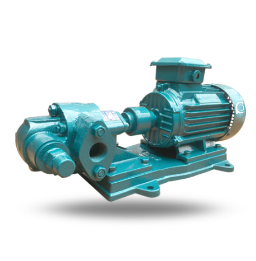
Product Overview
KCB/2CY Gear Oil Pump is a positive displacement pump designed for the transportation of lubricating oils, with a temperature range up to 70°C and the option for high-temperature configurations.
It addresses the need for reliable, stable flow in applications requiring high-viscosity liquids, with the added benefit of self-lubrication.
Ideal for use in petroleum, chemical, and lubrication systems where consistent oil transfer and flow stability are critical.
Model Designation

Specifications & Installation
Performance Parameters
|
Model
|
Motor Power (KW)
|
Speed (r/min)
|
Flow (L/min)
|
Discharge Pressure (MPa/cm2)
|
Max Suction Vacuum (m)
|
Inlet/Outlet Diameter
|
|
KCB18.3 (2CY-1.1/14.5-2)
|
1.5
|
1400
|
18.3
|
1.45
|
5
|
3/4″
|
|
KCB33.3 (2CY-2/14.5-2)
|
2.2
|
1420
|
33.3
|
1.45
|
5
|
3/4″
|
|
KCB55 (2CY-3.3/3.3-2)
|
1.5
|
1400
|
55
|
0.33
|
5
|
1″
|
|
KCB55 (2CY-3.3/3.5-2)
|
2.2
|
1420
|
55
|
0.5
|
5
|
1″
|
|
KCB83.3 (2CY-5/3-2)
|
2.2
|
1420
|
83.3
|
0.33
|
5
|
1.5″
|
|
KCB83.3 (2CY-5/5-2)
|
3
|
1420
|
83.3
|
0.5
|
5
|
1.5″
|
|
KCB200 (2CY-8/3.3-2)
|
4
|
1440
|
200
|
0.33
|
5
|
2″
|
|
KCB200 (2CY-12/1.3-2)
|
4
|
1440
|
200
|
0.13
|
5
|
2″
|
|
KCB200 (2CY-12/3.3-2)
|
5.5
|
1440
|
200
|
0.33
|
5
|
2″
|
|
KCB200 (2CY-12/6-2)
|
5.5
|
1440
|
200
|
0.60
|
5
|
2″
|
|
KCB200 (2CY-12/10-2)
|
7.5
|
1440
|
200
|
1.00
|
5
|
2″
|
How to Select a Pump Model
• Identify the required flow rate based on the lubrication needs of the system.
• Ensure the pump’s pressure rating is suitable for the operating conditions of the installation.
• Consider fluid viscosity to determine the best pump size and configuration.
• Select based on system redundancy and backup needs, especially for critical applications.
Engineering Notes
• Monitor oil temperature to ensure the pump operates within the optimal temperature range.
• Prevent dry-running by ensuring adequate liquid intake before starting the pump.
• Check for misalignment and adjust the flexible coupling as necessary to prevent damage.
• Perform regular maintenance to ensure the safety valve operates correctly and prevent system failures.
Compliance & Quality Assurance
• Factory performance testing ensures each pump meets specified flow and pressure standards.
• Hydraulic testing is conducted to verify the pump’s efficiency and durability.
• Material traceability for all wetted components ensures high standards of construction.
• Third-party inspection available for additional quality assurance.
Safety Notice
• Do not operate under dry-running conditions as this can damage the internal components.
• Ensure proper suction priming before starting the pump to avoid cavitation.
• Disconnect power before performing any maintenance or repairs.
• Ensure regular inspection of the safety valve to prevent overpressure situations.
OEM & Custom
This pump series supports engineered configuration and duty-based matching for various applications.
Available options include:
• Motor voltage & frequency
• Mechanical seal type and configuration
• Wetted parts material selection
• Surface coating and corrosion protection
FAQs
Q: What is the maximum viscosity that the pump can handle?
A: The pump is suitable for liquids with a viscosity of 5×10⁻⁵ to 1.5×10⁻³ m²/s.
Q: Can the pump operate under VFD control?
A: Yes, it is designed to operate efficiently with variable frequency drives.
Q: What is the maximum allowable operating pressure?
A: The pump operates safely under pressures up to 1.6 MPa.
Q: What materials are used for the wetted parts?
A: The wetted parts are typically made of cast iron and high-quality carbon steel.
Q: Is this pump suitable for transferring fuel oils?
A: Yes, the pump is suitable for fuel oils, as long as they are non-corrosive and free of hard particles.
Q: How often should the pump be serviced?
A: Regular maintenance should be performed every 6 months or after every 500,000 liters of transfer.