Product Overview
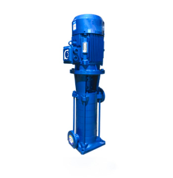
LG Vertical Split Multistage Clean Water Pump is a high-performance pump designed specifically for constant pressure water supply and fire protection systems in high-rise buildings. The system features an optimized hydraulic design, providing stable operational performance, low noise, long service life, and a compact footprint, making it ideal for building water supply systems that require efficiency, reliability, and long-term stability.
Model Designation

Key Features
-
Compact Vertical Design: This design is highly suitable for installation in pump rooms or spaces with limited area.
-
Efficient Operation: The impeller is directly mounted on the motor shaft, ensuring excellent concentricity, higher stability, and extended service life.
-
High Durability Sealing System: The system uses mechanical seals or combined sealing systems with high-quality alloy seals, offering excellent wear resistance.
-
Easy Installation and Maintenance: The same diameter for the inlet and discharge ports simplifies pipe connections, making installation and maintenance more convenient.
Engineering Summary
LG Pump Unit adopts a modular design, with rigid integration of the pressure tank and pump components. The optimized hydraulic model design ensures that the pump system operates efficiently and stably. The unit comes with standard configurations for easy installation and maintenance, while maintaining stability under high flow conditions.
Typical Applications
-
Constant pressure water supply systems for high-rise residential buildings and commercial buildings
-
Firefighting water supply and automatic sprinkler systems
-
Industrial and domestic water supply systems
System Configuration
Components & Supply
-
Pump Unit: LG Vertical Split Multistage Pump.
-
Motor: Standard Y-Series three-phase asynchronous motor.
-
Mechanical Seals: High-durability mechanical seal system.
-
Control System: PLC control system for automated operation.
Technical Services
Operating Conditions
-
Pumped Liquid: Suitable for clean water or liquids with similar chemical properties to water.
-
Viscosity: ≤150 mm²/s.
-
Operating Temperature Range: Standard type: –15°C to 80°C; Hot water version up to 105°C.
-
Maximum Operating Pressure: ≤2.5 MPa.
Service Conditions
-
Ambient Temperature: –15°C to +55°C.
-
Relative Humidity: ≤80%.
-
Maximum Operating Pressure: ≤2.5 MPa.
Protection Functions
-
Overpressure and Overheating Protection: Ensures safe operation of the pump and system components.
-
Automatic Start/Stop Function: Automatically starts and stops the pump based on pressure changes.
-
Leakage Protection: Prevents damage caused by system leakage.
-
Alarm System: Triggers visual and audible alarms in the event of faults.
Selection Criteria
-
Flow and Pressure Requirements: Select the appropriate model based on the system’s design flow and required pressure.
-
Installation Environment: Consider installation space and environmental requirements to ensure optimal operating conditions for the equipment.
-
Maintenance Requirements: Ensure the equipment has a simple maintenance process to minimize downtime.
Installation & Dimensions
Outline Drawing

Performance Data
| No. | Name | Material / Model | No. | Name | Material / Model |
| 1 | Motor | Y Series (V5), 2-Pole | 9 | Shaft Sleeve | Q235 |
| 2 | Motor Support | HT200 | 10 | Middle Section | HT200 |
| 3 | Coupling | HT200 | 11 | Guide Vane | HT200 |
| 4 | Mechanical Seal Gland | HT200 | 12 | Impeller | HT200 |
| 5 | Exhaust Valve | Brass Alloy | 13 | Shaft | 45 / 2Cr13 |
| 6 | Mechanical Seal | 120A | 14 | Bearing | Tin Bronze |
| 7 | Final Guide Vane | HT200 | 15 | Inlet Section | HT200 |
| 8 | Discharge Section | HT200 |
Performance Parameters
| Model | Stages | Flow Rate | Head | Speed | Motor Power | Efficiency | Weight | NPSHr |
| (m3/h) | (M) | (r/min) | (kw) | (%) | Kg | (NPSH)r(m) | ||
| 25LG(R)3-10*2 | 2 | 3 | 20 | 2900 | 0.75 | 42 | 70 | 2.0 |
| 25LG(R)3-10*3 | 3 | 3 | 30 | 2900 | 1.1 | 42 | 74 | 2.0 |
| 25LG(R)3-10*4 | 4 | 3 | 40 | 2900 | 1.5 | 42 | 85 | 2.0 |
| 25LG(R)3-10*5 | 5 | 3 | 50 | 2900 | 1.5 | 42 | 89 | 2.0 |
| 25LG(R)3-10*6 | 6 | 3 | 60 | 2900 | 2.2 | 42 | 100 | 2.0 |
| 25LG(R)3-10*7 | 7 | 3 | 70 | 2900 | 2.2 | 42 | 104 | 2.0 |
| 25LG(R)3-10*8 | 8 | 3 | 80 | 2900 | 2.2 | 42 | 108 | 2.0 |
| 25LG(R)3-10*9 | 9 | 3 | 90 | 2900 | 2.2 | 42 | 112 | 2.0 |
| 25LG(R)3-10*10 | 10 | 3 | 100 | 2900 | 3 | 42 | 125 | 2.0 |
| 25LG(R)3-10*11 | 11 | 3 | 110 | 2900 | 3 | 42 | 129 | 2.0 |
| 25LG(R)3-10*12 | 12 | 3 | 120 | 2900 | 4 | 42 | 145 | 2.0 |
| 25LG(R)3-10*13 | 13 | 3 | 130 | 2900 | 4 | 42 | 149 | 2.0 |
| 25LG(R)3-10*14 | 14 | 3 | 140 | 2900 | 4 | 42 | 153 | 2.0 |
| 25LG(R)3-10*15 | 15 | 3 | 150 | 2900 | 4 | 42 | 157 | 2.0 |
| Model | Stages | Flow Rate | Head | Speed | Motor Power | Efficiency | Weight | NPSHr |
| (m3/h) | (M) | (r/min) | (kw) | (%) | Kg | (NPSH)r(m) | ||
| 32LG(R)6.5-15*2 | 2 | 6.5 | 30 | 2900 | 1.5 | 53 | 90 | 2.4 |
| 32LG(R)6.5-15*3 | 3 | 6.5 | 45 | 2900 | 2.2 | 53 | 100 | 2.4 |
| 32LG(R)6.5-15*4 | 4 | 6.5 | 60 | 2900 | 3 | 53 | 115 | 2.4 |
| 32LG(R)6.5-15*5 | 5 | 6.5 | 75 | 2900 | 4 | 53 | 135 | 2.4 |
| 32LG(R)6.5-15*6 | 6 | 6.5 | 90 | 2900 | 4 | 53 | 142 | 2.4 |
| 32LG(R)6.5-15*7 | 7 | 6.5 | 105 | 2900 | 5.5 | 53 | 175 | 2.4 |
| 32LG(R)6.5-15*8 | 8 | 6.5 | 120 | 2900 | 5.5 | 53 | 182 | 2.4 |
| 32LG(R)6.5-15*9 | 9 | 6.5 | 135 | 2900 | 5.5 | 53 | 190 | 2.4 |
| 32LG(R)6.5-15*10 | 10 | 6.5 | 150 | 2900 | 7.5 | 53 | 210 | 2.4 |
| 40LG(R)12-15*2 | 2 | 12 | 30 | 2900 | 2.2 | 60 | 90 | 2.9 |
| 40LG(R)12-15*3 | 3 | 12 | 45 | 2900 | 3 | 60 | 105 | 2.9 |
| 40LG(R)12-15*4 | 4 | 12 | 60 | 2900 | 4 | 60 | 130 | 2.9 |
| 40LG(R)12-15*5 | 5 | 12 | 75 | 2900 | 5.5 | 60 | 155 | 2.9 |
| 40LG(R)12-15*6 | 6 | 12 | 90 | 2900 | 5.5 | 60 | 163 | 2.9 |
| 40LG(R)12-15*7 | 7 | 12 | 105 | 2900 | 7.5 | 60 | 180 | 2.9 |
| 40LG(R)12-15*8 | 8 | 12 | 120 | 2900 | 7.5 | 60 | 190 | 2.9 |
| 40LG(R)12-15*9 | 9 | 12 | 135 | 2900 | 11 | 60 | 215 | 2.9 |
| 40LG(R)12-15*10 | 10 | 12 | 150 | 2900 | 11 | 60 | 225 | 2.9 |
| Model | Stages | Flow Rate | Head | Speed | Motor Power | Efficiency | Weight | NPSHr |
| (m3/h) | (M) | (r/min) | (kw) | (%) | Kg | (NPSH)r(m) | ||
| 50LG(R)24-20*2 | 2 | 24 | 40 | 2900 | 5.5 | 69 | 160 | 3.2 |
| 50LG(R)24-20*3 | 3 | 24 | 60 | 2900 | 7.5 | 69 | 180 | 3.2 |
| 50LG(R)24-20*4 | 4 | 24 | 80 | 2900 | 11 | 69 | 250 | 3.2 |
| 50LG(R)24-20*5 | 5 | 24 | 100 | 2900 | 11 | 69 | 260 | 3.2 |
| 50LG(R)24-20*6 | 6 | 24 | 120 | 2900 | 15 | 69 | 280 | 3.2 |
| 50LG(R)24-20*7 | 7 | 24 | 140 | 2900 | 15 | 69 | 290 | 3.2 |
| 50LG(R)24-20*8 | 8 | 24 | 160 | 2900 | 18.5 | 69 | 315 | 3.2 |
| 65LG(R)36-20*2 | 2 | 36 | 40 | 2900 | 7.5 | 72 | 170 | 3.4 |
| 65LG(R)36-20*3 | 3 | 36 | 60 | 2900 | 11 | 72 | 230 | 3.4 |
| 65LG(R)36-20*4 | 4 | 36 | 80 | 2900 | 15 | 72 | 250 | 3.4 |
| 65LG(R)36-20*5 | 5 | 36 | 100 | 2900 | 18.5 | 72 | 280 | 3.4 |
| 65LG(R)36-20*6 | 6 | 36 | 120 | 2900 | 22 | 72 | 330 | 3.4 |
| 65LG(R)36-20*7 | 7 | 36 | 140 | 2900 | 22 | 72 | 345 | 3.4 |
| 65LG(R)36-20*8 | 8 | 36 | 160 | 2900 | 30 | 72 | 395 | 3.4 |
| Model | Stages | Flow Rate | Head | Speed | Motor Power | Efficiency | Weight | NPSHr |
| (m3/h) | (M) | (r/min) | (kw) | (%) | Kg | (NPSH)r(m) | ||
| 80LG(R)50-20*2 | 2 | 50 | 40 | 2900 | 11 | 73 | 250 | 3.4 |
| 80LG(R)50-20*3 | 3 | 50 | 60 | 2900 | 15 | 73 | 280 | 3.4 |
| 80LG(R)50-20*4 | 4 | 50 | 80 | 2900 | 18.5 | 73 | 310 | 3.4 |
| 80LG(R)50-20*5 | 5 | 50 | 100 | 2900 | 22 | 73 | 360 | 3.4 |
| 80LG(R)50-20*6 | 6 | 50 | 120 | 2900 | 30 | 73 | 440 | 3.4 |
| 80LG(R)50-20*7 | 7 | 50 | 140 | 2900 | 30 | 73 | 460 | |
| 80LG(R)50-20*8 | 8 | 50 | 160 | 2900 | 37 | 73 | 490 | |
| 100LG72-20*2 | 2 | 72 | 40 | 2900 | 11 | 73 | 260 | 3.5 |
| 100LG72-20*3 | 3 | 72 | 60 | 2900 | 18.5 | 73 | 290 | 3.5 |
| 100LG72-20*4 | 4 | 72 | 80 | 2900 | 22.0 | 73 | 380 | 3.5 |
| 100LG72-20*5 | 5 | 72 | 100 | 2900 | 30.0 | 73 | 450 | 3.5 |
| 100LG72-20*6 | 6 | 72 | 120 | 2900 | 37.0 | 73 | 470 | 3.5 |
| 100LG72-20*7 | 7 | 72 | 140 | 2900 | 45.0 | 73 | 520 | 3.5 |
| 100LG72-20*8 | 8 | 72 | 160 | 2900 | 45.0 | 73 | 540 | 3.5 |
| 100LG72-20*9 | 9 | 72 | 180 | 2900 | 55.0 | 73 | 3.5 | |
| Model | Stages | Flow Rate | Head | Speed | Motor Power | Efficiency | Weight | NPSHr |
| (m3/h) | (M) | (r/min) | (kw) | (%) | Kg | (NPSH)r(m) | ||
| 100LG100-20*2 | 2 | 100 | 40 | 2900 | 18.5 | 76 | 3.7 | |
| 100LG100-20*3 | 3 | 100 | 60 | 2900 | 30 | 76 | 3.7 | |
| 100LG100-20*4 | 4 | 100 | 80 | 2900 | 37 | 76 | 3.7 | |
| 100LG100-20*5 | 5 | 100 | 100 | 2900 | 45 | 76 | 3.7 | |
| 100LG100-20*6 | 6 | 100 | 120 | 2900 | 55 | 76 | 3.7 | |
| 100LG100-20*7 | 7 | 100 | 140 | 2900 | 75 | 76 | 3.7 | |
| 100LG100-20*8 | 8 | 100 | 160 | 2900 | 75 | 76 | 3.7 | |
| 150LG150-20*2 | 2 | 150 | 40 | 2900 | 30 | 77 | 4.1 | |
| 150LG150-20*3 | 3 | 150 | 60 | 2900 | 37 | 77 | 4.1 | |
| 150LG150-20*4 | 4 | 150 | 80 | 2900 | 45 | 77 | 4.1 | |
| 150LG150-20*5 | 5 | 150 | 100 | 2900 | 55 | 77 | 4.1 | |
| 150LG150-20*6 | 6 | 150 | 120 | 2900 | 75 | 77 | 4.1 | |
| 150LG150-20*7 | 7 | 150 | 140 | 2900 | 90 | 77 | 4.1 | |
| 150LG150-20*8 | 8 | 150 | 160 | 2900 | 90 | 77 | 4.1 | |
| 150LG150-20*9 | 9 | 150 | 180 | 2900 | 110 | 77 | 4.1 | |
| 150LG150-20*10 | 10 | 150 | 200 | 2900 | 132 | 77 | 4.1 |
Installation Diagram

Performance Parameters(2)
|
Model |
Stages | L | H | H1 | H2 | B | b | n-φd | Inlet Flange | Outlet Flange | ||||||
| Dj | Djn | Dj2 | n-dj | Dc | Dcn | Dc2 | n-φdc | |||||||||
| 25LG(R)3-10 | 2 | 130 | 630 | 85 | 180 | 230 | 190 | 4-φ18 | 115 | 25 | 85 | 4-M12 | 115 | 25 | 85 | 4-φ14 |
| 25LG(R)3-10 | 3 | 130 | 670 | 85 | 220 | 230 | 190 | 4-φ18 | 115 | 25 | 85 | 4-M12 | 115 | 25 | 85 | 4-φ14 |
| 25LG(R)3-10 | 4 | 130 | 710 | 85 | 260 | 230 | 190 | 4-φ18 | 115 | 25 | 85 | 4-M12 | 115 | 25 | 85 | 4-φ14 |
| 25LG(R)3-10 | 5 | 130 | 755 | 85 | 305 | 230 | 190 | 4-φ18 | 115 | 25 | 85 | 4-M12 | 115 | 25 | 85 | 4-φ14 |
| 25LG(R)3-10 | 6 | 130 | 825 | 85 | 340 | 230 | 190 | 4-φ18 | 115 | 25 | 85 | 4-M12 | 115 | 25 | 85 | 4-φ14 |
| 25LG(R)3-10 | 7 | 130 | 865 | 85 | 380 | 230 | 190 | 4-φ18 | 115 | 25 | 85 | 4-M12 | 115 | 25 | 85 | 4-φ14 |
| 25LG(R)3-10 | 8 | 130 | 900 | 85 | 425 | 230 | 190 | 4-φ18 | 115 | 25 | 85 | 4-M12 | 115 | 25 | 85 | 4-φ14 |
| 25LG(R)3-10 | 9 | 130 | 945 | 85 | 460 | 230 | 190 | 4-φ18 | 115 | 25 | 85 | 4-M12 | 115 | 25 | 85 | 4-φ14 |
| 25LG(R)3-10 | 10 | 130 | 1020 | 85 | 500 | 230 | 190 | 4-φ18 | 115 | 25 | 85 | 4-M12 | 115 | 25 | 85 | 4-φ14 |
| 25LG(R)3-10 | 11 | 130 | 1060 | 85 | 540 | 230 | 190 | 4-φ18 | 115 | 25 | 85 | 4-M12 | 115 | 25 | 85 | 4-φ14 |
| 25LG(R)3-10 | 12 | 130 | 1120 | 85 | 580 | 230 | 190 | 4-φ18 | 115 | 25 | 85 | 4-M12 | 115 | 25 | 85 | 4-φ14 |
| 25LG(R)3-10 | 13 | 130 | 1160 | 85 | 620 | 230 | 190 | 4-φ18 | 115 | 25 | 85 | 4-M12 | 115 | 25 | 85 | 4-φ14 |
| 25LG(R)3-10 | 14 | 130 | 1200 | 85 | 660 | 230 | 190 | 4-φ18 | 115 | 25 | 85 | 4-M12 | 115 | 25 | 85 | 4-φ14 |
| 25LG(R)3-10 | 15 | 130 | 1240 | 85 | 700 | 230 | 190 | 4-φ18 | 115 | 25 | 85 | 4-M12 | 115 | 25 | 85 | 4-φ14 |
|
Model |
Stages | L | H | H1 | H2 | B | b | n-φd | Inlet Flange | Outlet Flange | ||||||
| Dj | Djn | Dj2 | n-dj | Dc | Dcn | Dc2 | n-φdc | |||||||||
| 32LG(R)6.5-15 | 2 | 145 | 665 | 63 | 179 | 260 | 220 | 4-φ18 | 140 | 32 | 100 | 4-M16 | 140 | 32 | 100 | 4-φ18 |
| 32LG(R)6.5-15 | 3 | 145 | 740 | 63 | 229 | 260 | 220 | 4-φ18 | 140 | 32 | 100 | 4-M16 | 140 | 32 | 100 | 4-φ18 |
| 32LG(R)6.5-15 | 4 | 145 | 825 | 63 | 279 | 260 | 220 | 4-φ18 | 140 | 32 | 100 | 4-M16 | 140 | 32 | 100 | 4-φ18 |
| 32LG(R)6.5-15 | 5 | 145 | 895 | 63 | 329 | 260 | 220 | 4-φ18 | 140 | 32 | 100 | 4-M16 | 140 | 32 | 100 | 4-φ18 |
| 32LG(R)6.5-15 | 6 | 145 | 945 | 63 | 379 | 260 | 220 | 4-φ18 | 140 | 32 | 100 | 4-M16 | 140 | 32 | 100 | 4-φ18 |
| 32LG(R)6.5-15 | 7 | 145 | 1070 | 63 | 429 | 260 | 220 | 4-φ18 | 140 | 32 | 100 | 4-M16 | 140 | 32 | 100 | 4-φ18 |
| 32LG(R)6.5-15 | 8 | 145 | 1120 | 63 | 479 | 260 | 220 | 4-φ18 | 140 | 32 | 100 | 4-M16 | 140 | 32 | 100 | 4-φ18 |
| 32LG(R)6.5-15 | 9 | 145 | 1170 | 63 | 529 | 260 | 220 | 4-φ18 | 140 | 32 | 100 | 4-M16 | 140 | 32 | 100 | 4-φ18 |
| 32LG(R)6.5-15 | 10 | 145 | 1220 | 63 | 579 | 260 | 220 | 4-φ18 | 140 | 32 | 100 | 4-M16 | 140 | 32 | 100 | 4-φ18 |
| 40LG(R)12-15 | 2 | 145 | 710 | 70 | 193 | 260 | 220 | 4-φ18 | 150 | 40 | 110 | 4-M16 | 150 | 40 | 110 | 4-φ18 |
| 40LG(R)12-15 | 3 | 145 | 800 | 70 | 251 | 260 | 220 | 4-φ18 | 150 | 40 | 110 | 4-M16 | 150 | 40 | 110 | 4-φ18 |
| 40LG(R)12-15 | 4 | 145 | 880 | 70 | 309 | 260 | 220 | 4-φ18 | 150 | 40 | 110 | 4-M16 | 150 | 40 | 110 | 4-φ18 |
| 40LG(R)12-15 | 5 | 145 | 1015 | 70 | 367 | 260 | 220 | 4-φ18 | 150 | 40 | 110 | 4-M16 | 150 | 40 | 110 | 4-φ18 |
| 40LG(R)12-15 | 6 | 145 | 1075 | 70 | 425 | 260 | 220 | 4-φ18 | 150 | 40 | 110 | 4-M16 | 150 | 40 | 110 | 4-φ18 |
| 40LG(R)12-15 | 7 | 145 | 1170 | 70 | 483 | 260 | 220 | 4-φ18 | 150 | 40 | 110 | 4-M16 | 150 | 40 | 110 | 4-φ18 |
| 40LG(R)12-15 | 8 | 145 | 1230 | 70 | 541 | 260 | 220 | 4-φ18 | 150 | 40 | 110 | 4-M16 | 150 | 40 | 110 | 4-φ18 |
| 40LG(R)12-15 | 9 | 145 | 1410 | 70 | 599 | 260 | 220 | 4-φ18 | 150 | 40 | 110 | 4-M16 | 150 | 40 | 110 | 4-φ18 |
| 40LG(R)12-15 | 10 | 145 | 1465 | 70 | 657 | 260 | 220 | 4-φ18 | 150 | 40 | 110 | 4-M16 | 150 | 40 | 110 | 4-φ18 |
|
Model |
Stages | L | H | H1 | H2 | B | b | n-φd | Inlet Flange | Outlet Flange | ||||||
| Dj | Djn | Dj2 | n-dj | Dc | Dcn | Dc2 | n-φdc | |||||||||
| 50LG(R)24-20 | 2 | 180 | 885 | 80 | 214 | 300 | 248 | 4-φ23 | 165 | 50 | 125 | 4-M16 | 165 | 50 | 125 | 4-φ18 |
| 50LG(R)24-20 | 3 | 180 | 985 | 80 | 273 | 300 | 248 | 4-φ23 | 165 | 50 | 125 | 4-M16 | 165 | 50 | 125 | 4-φ18 |
| 50LG(R)24-20 | 4 | 180 | 1145 | 80 | 332 | 300 | 248 | 4-φ23 | 165 | 50 | 125 | 4-M16 | 165 | 50 | 125 | 4-φ18 |
| 50LG(R)24-20 | 5 | 180 | 1210 | 80 | 391 | 300 | 248 | 4-φ23 | 165 | 50 | 125 | 4-M16 | 165 | 50 | 125 | 4-φ18 |
| 50LG(R)24-20 | 6 | 180 | 1275 | 80 | 450 | 300 | 248 | 4-φ23 | 165 | 50 | 125 | 4-M16 | 165 | 50 | 125 | 4-φ18 |
| 50LG(R)24-20 | 7 | 180 | 1340 | 80 | 509 | 300 | 248 | 4-φ23 | 165 | 50 | 125 | 4-M16 | 165 | 50 | 125 | 4-φ18 |
| 50LG(R)24-20 | 8 | 180 | 1450 | 80 | 568 | 300 | 248 | 4-φ23 | 165 | 50 | 125 | 4-M16 | 165 | 50 | 125 | 4-φ18 |
| 65LG(R)36-20 | 2 | 180 | 965 | 90 | 245 | 300 | 248 | 4-φ23 | 185 | 65 | 145 | 4-M16 | 185 | 65 | 145 | 4-φ18 |
| 65LG(R)36-20 | 3 | 180 | 1120 | 90 | 304 | 300 | 248 | 4-φ23 | 185 | 65 | 145 | 4-M16 | 185 | 65 | 145 | 4-φ18 |
| 65LG(R)36-20 | 4 | 180 | 1185 | 90 | 363 | 300 | 248 | 4-φ23 | 185 | 65 | 145 | 4-M16 | 185 | 65 | 145 | 4-φ18 |
| 65LG(R)36-20 | 5 | 180 | 1295 | 90 | 422 | 300 | 248 | 4-φ23 | 185 | 65 | 145 | 4-M16 | 185 | 65 | 145 | 4-φ18 |
| 65LG(R)36-20 | 6 | 180 | 1390 | 90 | 481 | 300 | 248 | 4-φ23 | 185 | 65 | 145 | 4-M16 | 185 | 65 | 145 | 4-φ18 |
| 65LG(R)36-20 | 7 | 180 | 1455 | 90 | 540 | 300 | 248 | 4-φ23 | 185 | 65 | 145 | 4-M16 | 185 | 65 | 145 | 4-φ18 |
| 65LG(R)36-20 | 8 | 180 | 1615 | 90 | 599 | 300 | 248 | 4-φ23 | 185 | 65 | 145 | 4-M16 | 185 | 65 | 145 | 4-φ18 |
|
Model |
Stages | L | H | H1 | H2 | B | b | n-φd | Inlet Flange | Outlet Flange | ||||||
| Dj | Djn | Dj2 | n-dj | Dc | Dcn | Dc2 | n-φdc | |||||||||
| 80LG(R)50-20 | 2 | 187 | 965 | 112 | 301 | 315 | 272 | 4-φ23 | 200 | 80 | 160 | 8-M16 | 200 | 80 | 160 | 8-φ18 |
| 80LG(R)50-20 | 3 | 187 | 1195 | 112 | 379 | 315 | 272 | 4-φ23 | 200 | 80 | 160 | 8-M16 | 200 | 80 | 160 | 8-φ18 |
| 80LG(R)50-20 | 4 | 187 | 1270 | 112 | 457 | 315 | 272 | 4-φ23 | 200 | 80 | 160 | 8-M16 | 200 | 80 | 160 | 8-φ18 |
| 80LG(R)50-20 | 5 | 187 | 1395 | 112 | 535 | 315 | 272 | 4-φ23 | 200 | 80 | 160 | 8-M16 | 200 | 80 | 160 | 8-φ18 |
| 80LG(R)50-20 | 6 | 187 | 1505 | 112 | 613 | 315 | 272 | 4-φ23 | 200 | 80 | 160 | 8-M16 | 200 | 80 | 160 | 8-φ18 |
| 80LG(R)50-20 | 7 | 187 | 1675 | 112 | 691 | 315 | 272 | 4-φ23 | 200 | 80 | 160 | 8-M16 | 200 | 80 | 160 | 8-φ18 |
| 80LG(R)50-20 | 8 | 187 | 1755 | 112 | 769 | 315 | 272 | 4-φ23 | 200 | 80 | 160 | 8-M16 | 200 | 80 | 160 | 8-φ18 |
| 100LG72-20 | 2 | 187 | 1185 | 122 | 343 | 315 | 272 | 4-φ23 | 220 | 100 | 180 | 8-M16 | 220 | 100 | 180 | 8-φ18 |
| 100LG72-20 | 3 | 187 | 1270 | 122 | 432 | 315 | 272 | 4-φ23 | 220 | 100 | 180 | 8-M16 | 220 | 100 | 180 | 8-φ18 |
| 100LG72-20 | 4 | 187 | 1390 | 122 | 521 | 315 | 272 | 4-φ23 | 220 | 100 | 180 | 8-M16 | 220 | 100 | 180 | 8-φ18 |
| 100LG72-20 | 5 | 187 | 1580 | 122 | 610 | 315 | 272 | 4-φ23 | 220 | 100 | 180 | 8-M16 | 220 | 100 | 180 | 8-φ18 |
| 100LG72-20 | 6 | 187 | 1655 | 122 | 699 | 315 | 272 | 4-φ23 | 220 | 100 | 180 | 8-M16 | 220 | 100 | 180 | 8-φ18 |
| 100LG72-20 | 7 | 187 | 1800 | 122 | 788 | 315 | 272 | 4-φ23 | 220 | 100 | 180 | 8-M16 | 220 | 100 | 180 | 8-φ18 |
| 100LG72-20 | 8 | 187 | 1900 | 122 | 877 | 315 | 272 | 4-φ23 | 220 | 100 | 180 | 8-M16 | 220 | 100 | 180 | 8-φ18 |
| 100LG72-20 | 9 | 187 | 2100 | 122 | 966 | 315 | 272 | 4-φ23 | 220 | 100 | 180 | 8-M16 | 220 | 100 | 180 | 8-φ18 |
Installation Diagram(2)
|
|
|||||||||||||||||||||||||||||||||||||||||||||||||||||||||||||||||||||||||


Installation Diagram(3)
|
|
|||||||||||||||||||||||||||||||||||||


Performance Data(2)
|
||||||||||||||||||||||||||||||||||||||||||||||||||||||||||||||||||||||||||||||||||||||||||||||||||||||||||||||||||||||
FAQs
- Q: What’s the main application of the LG-B pump?
A: Mainly used for high-rise building water supply, fire-fighting, HVAC, and boiler feed systems. - Q: What’s the maximum working temperature?
A: Standard model ≤120°C, suitable for clean or slightly hot water. - Q: Is the pump easy to maintain?
A: Yes, the detachable design allows easy servicing without pipeline removal. - Q: Can it operate continuously?
A: Yes, designed for 24-hour operation with stable hydraulic performance. - Q: What’s the system pressure range?
A: Standard ≤2.5 MPa, with optional higher pressure versions available. - Q: Do you provide OEM options?
A: Yes, full OEM/ODM service including labeling and packaging customization. - Q: Which markets use this pump?
A: Exported to Southeast Asia, the Middle East, and Africa for building and municipal systems.