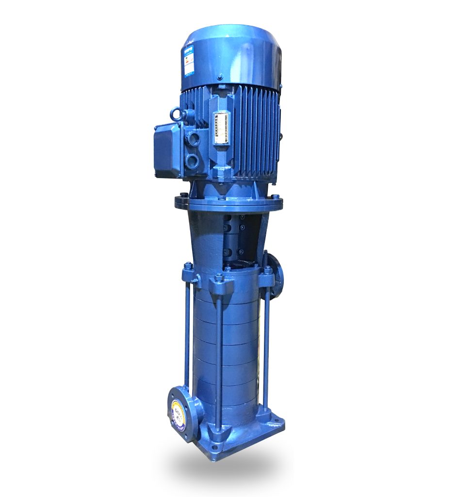
Product Overview
The LG vertical, easy-dismantling multistage clean-water pump is an integrated vertical multistage pump unit developed for constant-pressure water supply in high-rise buildings and for fire-fighting duties. Based on a proven hydraulic design, it delivers high efficiency and stable head–capacity characteristics, making it suitable for continuous operation with low noise and long service life. The vertical multistage configuration provides a compact footprint and enables straightforward integration into building booster systems and packaged pump sets. With a lightweight, service-friendly component layout, the unit is well suited for engineering installations in building water supply, drainage, and building services systems.
Model Designation

Key Features
- Compact vertical multistage structure with a small footprint, suitable for building water systems; optional outdoor protection cover supports flexible installation scenarios.
- Impellers directly mounted on motor shaft ensure coaxial operation, enhancing stability and extending equipment service life.
- High-quality mechanical seal or cartridge seal, equipped with hard alloy sealing rings for improved wear resistance and extended seal durability.
- Equal-diameter suction/discharge ports, support for series or parallel pump operation, configurable inlet/outlet orientation (0°, 90°, 180°, 270°), and head adjustability via stage modification or impeller trimming.
Installation Dimensions/Size
Outline Drawing

Pump Parts & Materials List
| Item No. | Component Name | Material / Model | Item No. | Component Name | Material / Model |
|---|---|---|---|---|---|
| 1 | Motor | Y Series (V5), 2-Pole | 9 | Shaft Sleeve | Q235 |
| 2 | Motor Bracket | HT200 | 10 | Middle Section | HT200 |
| 3 | Coupling | HT200 | 11 | Diffuser | HT200 |
| 4 | Mechanical Seal Cover | HT200 | 12 | Impeller | HT200 |
| 5 | Air Release Valve | Copper Alloy | 13 | Shaft | 45 Steel / 2Cr13 |
| 6 | Mechanical Seal | 120A | 14 | Bearing | Tin Bronze |
| 7 | Final Diffuser | HT200 | 15 | Suction Section | HT200 |
| 8 | Discharge Section | HT200 |
Performance Parameters
| Model | Stages | Flow | Head | Speed | Motor Power | Efficiency | Weight | Required |
| (m3/h) | (M) | (r/min) | (kw) | (%) | Kg | NPSH(m) | ||
| 25LG(R)3-10*2 | 2 | 3 | 20 | 2900 | 0.75 | 42 | 70 | 2.0 |
| 25LG(R)3-10*3 | 3 | 3 | 30 | 2900 | 1.1 | 42 | 74 | 2.0 |
| 25LG(R)3-10*4 | 4 | 3 | 40 | 2900 | 1.5 | 42 | 85 | 2.0 |
| 25LG(R)3-10*5 | 5 | 3 | 50 | 2900 | 1.5 | 42 | 89 | 2.0 |
| 25LG(R)3-10*6 | 6 | 3 | 60 | 2900 | 2.2 | 42 | 100 | 2.0 |
| 25LG(R)3-10*7 | 7 | 3 | 70 | 2900 | 2.2 | 42 | 104 | 2.0 |
| 25LG(R)3-10*8 | 8 | 3 | 80 | 2900 | 2.2 | 42 | 108 | 2.0 |
| 25LG(R)3-10*9 | 9 | 3 | 90 | 2900 | 2.2 | 42 | 112 | 2.0 |
| 25LG(R)3-10*10 | 10 | 3 | 100 | 2900 | 3 | 42 | 125 | 2.0 |
| 25LG(R)3-10*11 | 11 | 3 | 110 | 2900 | 3 | 42 | 129 | 2.0 |
| 25LG(R)3-10*12 | 12 | 3 | 120 | 2900 | 4 | 42 | 145 | 2.0 |
| 25LG(R)3-10*13 | 13 | 3 | 130 | 2900 | 4 | 42 | 149 | 2.0 |
| 25LG(R)3-10*14 | 14 | 3 | 140 | 2900 | 4 | 42 | 153 | 2.0 |
| 25LG(R)3-10*15 | 15 | 3 | 150 | 2900 | 4 | 42 | 157 | 2.0 |
| Model | Stages | Flow | Head | Speed | Motor Power | Efficiency | Weight | Required |
| (m3/h) | (M) | (r/min) | (kw) | (%) | Kg | NPSH(m) | ||
| 32LG(R)6.5-15*2 | 2 | 6.5 | 30 | 2900 | 1.5 | 53 | 90 | 2.4 |
| 32LG(R)6.5-15*3 | 3 | 6.5 | 45 | 2900 | 2.2 | 53 | 100 | 2.4 |
| 32LG(R)6.5-15*4 | 4 | 6.5 | 60 | 2900 | 3 | 53 | 115 | 2.4 |
| 32LG(R)6.5-15*5 | 5 | 6.5 | 75 | 2900 | 4 | 53 | 135 | 2.4 |
| 32LG(R)6.5-15*6 | 6 | 6.5 | 90 | 2900 | 4 | 53 | 142 | 2.4 |
| 32LG(R)6.5-15*7 | 7 | 6.5 | 105 | 2900 | 5.5 | 53 | 175 | 2.4 |
| 32LG(R)6.5-15*8 | 8 | 6.5 | 120 | 2900 | 5.5 | 53 | 182 | 2.4 |
| 32LG(R)6.5-15*9 | 9 | 6.5 | 135 | 2900 | 5.5 | 53 | 190 | 2.4 |
| 32LG(R)6.5-15*10 | 10 | 6.5 | 150 | 2900 | 7.5 | 53 | 210 | 2.4 |
| 40LG(R)12-15*2 | 2 | 12 | 30 | 2900 | 2.2 | 60 | 90 | 2.9 |
| 40LG(R)12-15*3 | 3 | 12 | 45 | 2900 | 3 | 60 | 105 | 2.9 |
| 40LG(R)12-15*4 | 4 | 12 | 60 | 2900 | 4 | 60 | 130 | 2.9 |
| 40LG(R)12-15*5 | 5 | 12 | 75 | 2900 | 5.5 | 60 | 155 | 2.9 |
| 40LG(R)12-15*6 | 6 | 12 | 90 | 2900 | 5.5 | 60 | 163 | 2.9 |
| 40LG(R)12-15*7 | 7 | 12 | 105 | 2900 | 7.5 | 60 | 180 | 2.9 |
| 40LG(R)12-15*8 | 8 | 12 | 120 | 2900 | 7.5 | 60 | 190 | 2.9 |
| 40LG(R)12-15*9 | 9 | 12 | 135 | 2900 | 11 | 60 | 215 | 2.9 |
| 40LG(R)12-15*10 | 10 | 12 | 150 | 2900 | 11 | 60 | 225 | 2.9 |
| Model | Stages | Flow | Head | Speed | Motor Power | Efficiency | Weight | Required |
| (m3/h) | (M) | (r/min) | (kw) | (%) | Kg | NPSH(m) | ||
| 50LG(R)24-20*2 | 2 | 24 | 40 | 2900 | 5.5 | 69 | 160 | 3.2 |
| 50LG(R)24-20*3 | 3 | 24 | 60 | 2900 | 7.5 | 69 | 180 | 3.2 |
| 50LG(R)24-20*4 | 4 | 24 | 80 | 2900 | 11 | 69 | 250 | 3.2 |
| 50LG(R)24-20*5 | 5 | 24 | 100 | 2900 | 11 | 69 | 260 | 3.2 |
| 50LG(R)24-20*6 | 6 | 24 | 120 | 2900 | 15 | 69 | 280 | 3.2 |
| 50LG(R)24-20*7 | 7 | 24 | 140 | 2900 | 15 | 69 | 290 | 3.2 |
| 50LG(R)24-20*8 | 8 | 24 | 160 | 2900 | 18.5 | 69 | 315 | 3.2 |
| 65LG(R)36-20*2 | 2 | 36 | 40 | 2900 | 7.5 | 72 | 170 | 3.4 |
| 65LG(R)36-20*3 | 3 | 36 | 60 | 2900 | 11 | 72 | 230 | 3.4 |
| 65LG(R)36-20*4 | 4 | 36 | 80 | 2900 | 15 | 72 | 250 | 3.4 |
| 65LG(R)36-20*5 | 5 | 36 | 100 | 2900 | 18.5 | 72 | 280 | 3.4 |
| 65LG(R)36-20*6 | 6 | 36 | 120 | 2900 | 22 | 72 | 330 | 3.4 |
| 65LG(R)36-20*7 | 7 | 36 | 140 | 2900 | 22 | 72 | 345 | 3.4 |
| 65LG(R)36-20*8 | 8 | 36 | 160 | 2900 | 30 | 72 | 395 | 3.4 |
| Model | Stages | Flow | Head | Speed | Motor Power | Efficiency | Weight | Required |
| (m3/h) | (M) | (r/min) | (kw) | (%) | Kg | NPSH(m) | ||
| 80LG(R)50-20*2 | 2 | 50 | 40 | 2900 | 11 | 73 | 250 | 3.4 |
| 80LG(R)50-20*3 | 3 | 50 | 60 | 2900 | 15 | 73 | 280 | 3.4 |
| 80LG(R)50-20*4 | 4 | 50 | 80 | 2900 | 18.5 | 73 | 310 | 3.4 |
| 80LG(R)50-20*5 | 5 | 50 | 100 | 2900 | 22 | 73 | 360 | 3.4 |
| 80LG(R)50-20*6 | 6 | 50 | 120 | 2900 | 30 | 73 | 440 | 3.4 |
| 80LG(R)50-20*7 | 7 | 50 | 140 | 2900 | 30 | 73 | 460 | |
| 80LG(R)50-20*8 | 8 | 50 | 160 | 2900 | 37 | 73 | 490 | |
| 100LG72-20*2 | 2 | 72 | 40 | 2900 | 11 | 73 | 260 | 3.5 |
| 100LG72-20*3 | 3 | 72 | 60 | 2900 | 18.5 | 73 | 290 | 3.5 |
| 100LG72-20*4 | 4 | 72 | 80 | 2900 | 22.0 | 73 | 380 | 3.5 |
| 100LG72-20*5 | 5 | 72 | 100 | 2900 | 30.0 | 73 | 450 | 3.5 |
| 100LG72-20*6 | 6 | 72 | 120 | 2900 | 37.0 | 73 | 470 | 3.5 |
| 100LG72-20*7 | 7 | 72 | 140 | 2900 | 45.0 | 73 | 520 | 3.5 |
| 100LG72-20*8 | 8 | 72 | 160 | 2900 | 45.0 | 73 | 540 | 3.5 |
| 100LG72-20*9 | 9 | 72 | 180 | 2900 | 55.0 | 73 | 3.5 | |
| Model | Stages | Flow | Head | Speed | Motor Power | Efficiency | Weight | Required |
| (m3/h) | (M) | (r/min) | (kw) | (%) | Kg | NPSH(m) | ||
| 100LG100-20*2 | 2 | 100 | 40 | 2900 | 18.5 | 76 | 3.7 | |
| 100LG100-20*3 | 3 | 100 | 60 | 2900 | 30 | 76 | 3.7 | |
| 100LG100-20*4 | 4 | 100 | 80 | 2900 | 37 | 76 | 3.7 | |
| 100LG100-20*5 | 5 | 100 | 100 | 2900 | 45 | 76 | 3.7 | |
| 100LG100-20*6 | 6 | 100 | 120 | 2900 | 55 | 76 | 3.7 | |
| 100LG100-20*7 | 7 | 100 | 140 | 2900 | 75 | 76 | 3.7 | |
| 100LG100-20*8 | 8 | 100 | 160 | 2900 | 75 | 76 | 3.7 | |
| 150LG150-20*2 | 2 | 150 | 40 | 2900 | 30 | 77 | 4.1 | |
| 150LG150-20*3 | 3 | 150 | 60 | 2900 | 37 | 77 | 4.1 | |
| 150LG150-20*4 | 4 | 150 | 80 | 2900 | 45 | 77 | 4.1 | |
| 150LG150-20*5 | 5 | 150 | 100 | 2900 | 55 | 77 | 4.1 | |
| 150LG150-20*6 | 6 | 150 | 120 | 2900 | 75 | 77 | 4.1 | |
| 150LG150-20*7 | 7 | 150 | 140 | 2900 | 90 | 77 | 4.1 | |
| 150LG150-20*8 | 8 | 150 | 160 | 2900 | 90 | 77 | 4.1 | |
| 150LG150-20*9 | 9 | 150 | 180 | 2900 | 110 | 77 | 4.1 | |
| 150LG150-20*10 | 10 | 150 | 200 | 2900 | 132 | 77 | 4.1 |
Installation Diagram

Installation Dimensions(1)
|
Model |
Stages | L | H | H1 | H2 | B | b | n-φd | Inlet Flange | Outlet Flange | ||||||
| Dj | Djn | Dj2 | n-dj | Dc | Dcn | Dc2 | n-φdc | |||||||||
| 25LG(R)3-10 | 2 | 130 | 630 | 85 | 180 | 230 | 190 | 4-φ18 | 115 | 25 | 85 | 4-M12 | 115 | 25 | 85 | 4-φ14 |
| 25LG(R)3-10 | 3 | 130 | 670 | 85 | 220 | 230 | 190 | 4-φ18 | 115 | 25 | 85 | 4-M12 | 115 | 25 | 85 | 4-φ14 |
| 25LG(R)3-10 | 4 | 130 | 710 | 85 | 260 | 230 | 190 | 4-φ18 | 115 | 25 | 85 | 4-M12 | 115 | 25 | 85 | 4-φ14 |
| 25LG(R)3-10 | 5 | 130 | 755 | 85 | 305 | 230 | 190 | 4-φ18 | 115 | 25 | 85 | 4-M12 | 115 | 25 | 85 | 4-φ14 |
| 25LG(R)3-10 | 6 | 130 | 825 | 85 | 340 | 230 | 190 | 4-φ18 | 115 | 25 | 85 | 4-M12 | 115 | 25 | 85 | 4-φ14 |
| 25LG(R)3-10 | 7 | 130 | 865 | 85 | 380 | 230 | 190 | 4-φ18 | 115 | 25 | 85 | 4-M12 | 115 | 25 | 85 | 4-φ14 |
| 25LG(R)3-10 | 8 | 130 | 900 | 85 | 425 | 230 | 190 | 4-φ18 | 115 | 25 | 85 | 4-M12 | 115 | 25 | 85 | 4-φ14 |
| 25LG(R)3-10 | 9 | 130 | 945 | 85 | 460 | 230 | 190 | 4-φ18 | 115 | 25 | 85 | 4-M12 | 115 | 25 | 85 | 4-φ14 |
| 25LG(R)3-10 | 10 | 130 | 1020 | 85 | 500 | 230 | 190 | 4-φ18 | 115 | 25 | 85 | 4-M12 | 115 | 25 | 85 | 4-φ14 |
| 25LG(R)3-10 | 11 | 130 | 1060 | 85 | 540 | 230 | 190 | 4-φ18 | 115 | 25 | 85 | 4-M12 | 115 | 25 | 85 | 4-φ14 |
| 25LG(R)3-10 | 12 | 130 | 1120 | 85 | 580 | 230 | 190 | 4-φ18 | 115 | 25 | 85 | 4-M12 | 115 | 25 | 85 | 4-φ14 |
| 25LG(R)3-10 | 13 | 130 | 1160 | 85 | 620 | 230 | 190 | 4-φ18 | 115 | 25 | 85 | 4-M12 | 115 | 25 | 85 | 4-φ14 |
| 25LG(R)3-10 | 14 | 130 | 1200 | 85 | 660 | 230 | 190 | 4-φ18 | 115 | 25 | 85 | 4-M12 | 115 | 25 | 85 | 4-φ14 |
| 25LG(R)3-10 | 15 | 130 | 1240 | 85 | 700 | 230 | 190 | 4-φ18 | 115 | 25 | 85 | 4-M12 | 115 | 25 | 85 | 4-φ14 |
|
Model |
Stages | L | H | H1 | H2 | B | b | n-φd | Inlet Flange | Outlet Flange | ||||||
| Dj | Djn | Dj2 | n-dj | Dc | Dcn | Dc2 | n-φdc | |||||||||
| 32LG(R)6.5-15 | 2 | 145 | 665 | 63 | 179 | 260 | 220 | 4-φ18 | 140 | 32 | 100 | 4-M16 | 140 | 32 | 100 | 4-φ18 |
| 32LG(R)6.5-15 | 3 | 145 | 740 | 63 | 229 | 260 | 220 | 4-φ18 | 140 | 32 | 100 | 4-M16 | 140 | 32 | 100 | 4-φ18 |
| 32LG(R)6.5-15 | 4 | 145 | 825 | 63 | 279 | 260 | 220 | 4-φ18 | 140 | 32 | 100 | 4-M16 | 140 | 32 | 100 | 4-φ18 |
| 32LG(R)6.5-15 | 5 | 145 | 895 | 63 | 329 | 260 | 220 | 4-φ18 | 140 | 32 | 100 | 4-M16 | 140 | 32 | 100 | 4-φ18 |
| 32LG(R)6.5-15 | 6 | 145 | 945 | 63 | 379 | 260 | 220 | 4-φ18 | 140 | 32 | 100 | 4-M16 | 140 | 32 | 100 | 4-φ18 |
| 32LG(R)6.5-15 | 7 | 145 | 1070 | 63 | 429 | 260 | 220 | 4-φ18 | 140 | 32 | 100 | 4-M16 | 140 | 32 | 100 | 4-φ18 |
| 32LG(R)6.5-15 | 8 | 145 | 1120 | 63 | 479 | 260 | 220 | 4-φ18 | 140 | 32 | 100 | 4-M16 | 140 | 32 | 100 | 4-φ18 |
| 32LG(R)6.5-15 | 9 | 145 | 1170 | 63 | 529 | 260 | 220 | 4-φ18 | 140 | 32 | 100 | 4-M16 | 140 | 32 | 100 | 4-φ18 |
| 32LG(R)6.5-15 | 10 | 145 | 1220 | 63 | 579 | 260 | 220 | 4-φ18 | 140 | 32 | 100 | 4-M16 | 140 | 32 | 100 | 4-φ18 |
| 40LG(R)12-15 | 2 | 145 | 710 | 70 | 193 | 260 | 220 | 4-φ18 | 150 | 40 | 110 | 4-M16 | 150 | 40 | 110 | 4-φ18 |
| 40LG(R)12-15 | 3 | 145 | 800 | 70 | 251 | 260 | 220 | 4-φ18 | 150 | 40 | 110 | 4-M16 | 150 | 40 | 110 | 4-φ18 |
| 40LG(R)12-15 | 4 | 145 | 880 | 70 | 309 | 260 | 220 | 4-φ18 | 150 | 40 | 110 | 4-M16 | 150 | 40 | 110 | 4-φ18 |
| 40LG(R)12-15 | 5 | 145 | 1015 | 70 | 367 | 260 | 220 | 4-φ18 | 150 | 40 | 110 | 4-M16 | 150 | 40 | 110 | 4-φ18 |
| 40LG(R)12-15 | 6 | 145 | 1075 | 70 | 425 | 260 | 220 | 4-φ18 | 150 | 40 | 110 | 4-M16 | 150 | 40 | 110 | 4-φ18 |
| 40LG(R)12-15 | 7 | 145 | 1170 | 70 | 483 | 260 | 220 | 4-φ18 | 150 | 40 | 110 | 4-M16 | 150 | 40 | 110 | 4-φ18 |
| 40LG(R)12-15 | 8 | 145 | 1230 | 70 | 541 | 260 | 220 | 4-φ18 | 150 | 40 | 110 | 4-M16 | 150 | 40 | 110 | 4-φ18 |
| 40LG(R)12-15 | 9 | 145 | 1410 | 70 | 599 | 260 | 220 | 4-φ18 | 150 | 40 | 110 | 4-M16 | 150 | 40 | 110 | 4-φ18 |
| 40LG(R)12-15 | 10 | 145 | 1465 | 70 | 657 | 260 | 220 | 4-φ18 | 150 | 40 | 110 | 4-M16 | 150 | 40 | 110 | 4-φ18 |
|
Model |
Stages | L | H | H1 | H2 | B | b | n-φd | Inlet Flange | Outlet Flange | ||||||
| Dj | Djn | Dj2 | n-dj | Dc | Dcn | Dc2 | n-φdc | |||||||||
| 50LG(R)24-20 | 2 | 180 | 885 | 80 | 214 | 300 | 248 | 4-φ23 | 165 | 50 | 125 | 4-M16 | 165 | 50 | 125 | 4-φ18 |
| 50LG(R)24-20 | 3 | 180 | 985 | 80 | 273 | 300 | 248 | 4-φ23 | 165 | 50 | 125 | 4-M16 | 165 | 50 | 125 | 4-φ18 |
| 50LG(R)24-20 | 4 | 180 | 1145 | 80 | 332 | 300 | 248 | 4-φ23 | 165 | 50 | 125 | 4-M16 | 165 | 50 | 125 | 4-φ18 |
| 50LG(R)24-20 | 5 | 180 | 1210 | 80 | 391 | 300 | 248 | 4-φ23 | 165 | 50 | 125 | 4-M16 | 165 | 50 | 125 | 4-φ18 |
| 50LG(R)24-20 | 6 | 180 | 1275 | 80 | 450 | 300 | 248 | 4-φ23 | 165 | 50 | 125 | 4-M16 | 165 | 50 | 125 | 4-φ18 |
| 50LG(R)24-20 | 7 | 180 | 1340 | 80 | 509 | 300 | 248 | 4-φ23 | 165 | 50 | 125 | 4-M16 | 165 | 50 | 125 | 4-φ18 |
| 50LG(R)24-20 | 8 | 180 | 1450 | 80 | 568 | 300 | 248 | 4-φ23 | 165 | 50 | 125 | 4-M16 | 165 | 50 | 125 | 4-φ18 |
| 65LG(R)36-20 | 2 | 180 | 965 | 90 | 245 | 300 | 248 | 4-φ23 | 185 | 65 | 145 | 4-M16 | 185 | 65 | 145 | 4-φ18 |
| 65LG(R)36-20 | 3 | 180 | 1120 | 90 | 304 | 300 | 248 | 4-φ23 | 185 | 65 | 145 | 4-M16 | 185 | 65 | 145 | 4-φ18 |
| 65LG(R)36-20 | 4 | 180 | 1185 | 90 | 363 | 300 | 248 | 4-φ23 | 185 | 65 | 145 | 4-M16 | 185 | 65 | 145 | 4-φ18 |
| 65LG(R)36-20 | 5 | 180 | 1295 | 90 | 422 | 300 | 248 | 4-φ23 | 185 | 65 | 145 | 4-M16 | 185 | 65 | 145 | 4-φ18 |
| 65LG(R)36-20 | 6 | 180 | 1390 | 90 | 481 | 300 | 248 | 4-φ23 | 185 | 65 | 145 | 4-M16 | 185 | 65 | 145 | 4-φ18 |
| 65LG(R)36-20 | 7 | 180 | 1455 | 90 | 540 | 300 | 248 | 4-φ23 | 185 | 65 | 145 | 4-M16 | 185 | 65 | 145 | 4-φ18 |
| 65LG(R)36-20 | 8 | 180 | 1615 | 90 | 599 | 300 | 248 | 4-φ23 | 185 | 65 | 145 | 4-M16 | 185 | 65 | 145 | 4-φ18 |
|
Model |
Stages | L | H | H1 | H2 | B | b | n-φd | Inlet Flange | Outlet Flange | ||||||
| Dj | Djn | Dj2 | n-dj | Dc | Dcn | Dc2 | n-φdc | |||||||||
| 80LG(R)50-20 | 2 | 187 | 965 | 112 | 301 | 315 | 272 | 4-φ23 | 200 | 80 | 160 | 8-M16 | 200 | 80 | 160 | 8-φ18 |
| 80LG(R)50-20 | 3 | 187 | 1195 | 112 | 379 | 315 | 272 | 4-φ23 | 200 | 80 | 160 | 8-M16 | 200 | 80 | 160 | 8-φ18 |
| 80LG(R)50-20 | 4 | 187 | 1270 | 112 | 457 | 315 | 272 | 4-φ23 | 200 | 80 | 160 | 8-M16 | 200 | 80 | 160 | 8-φ18 |
| 80LG(R)50-20 | 5 | 187 | 1395 | 112 | 535 | 315 | 272 | 4-φ23 | 200 | 80 | 160 | 8-M16 | 200 | 80 | 160 | 8-φ18 |
| 80LG(R)50-20 | 6 | 187 | 1505 | 112 | 613 | 315 | 272 | 4-φ23 | 200 | 80 | 160 | 8-M16 | 200 | 80 | 160 | 8-φ18 |
| 80LG(R)50-20 | 7 | 187 | 1675 | 112 | 691 | 315 | 272 | 4-φ23 | 200 | 80 | 160 | 8-M16 | 200 | 80 | 160 | 8-φ18 |
| 80LG(R)50-20 | 8 | 187 | 1755 | 112 | 769 | 315 | 272 | 4-φ23 | 200 | 80 | 160 | 8-M16 | 200 | 80 | 160 | 8-φ18 |
| 100LG72-20 | 2 | 187 | 1185 | 122 | 343 | 315 | 272 | 4-φ23 | 220 | 100 | 180 | 8-M16 | 220 | 100 | 180 | 8-φ18 |
| 100LG72-20 | 3 | 187 | 1270 | 122 | 432 | 315 | 272 | 4-φ23 | 220 | 100 | 180 | 8-M16 | 220 | 100 | 180 | 8-φ18 |
| 100LG72-20 | 4 | 187 | 1390 | 122 | 521 | 315 | 272 | 4-φ23 | 220 | 100 | 180 | 8-M16 | 220 | 100 | 180 | 8-φ18 |
| 100LG72-20 | 5 | 187 | 1580 | 122 | 610 | 315 | 272 | 4-φ23 | 220 | 100 | 180 | 8-M16 | 220 | 100 | 180 | 8-φ18 |
| 100LG72-20 | 6 | 187 | 1655 | 122 | 699 | 315 | 272 | 4-φ23 | 220 | 100 | 180 | 8-M16 | 220 | 100 | 180 | 8-φ18 |
| 100LG72-20 | 7 | 187 | 1800 | 122 | 788 | 315 | 272 | 4-φ23 | 220 | 100 | 180 | 8-M16 | 220 | 100 | 180 | 8-φ18 |
| 100LG72-20 | 8 | 187 | 1900 | 122 | 877 | 315 | 272 | 4-φ23 | 220 | 100 | 180 | 8-M16 | 220 | 100 | 180 | 8-φ18 |
| 100LG72-20 | 9 | 187 | 2100 | 122 | 966 | 315 | 272 | 4-φ23 | 220 | 100 | 180 | 8-M16 | 220 | 100 | 180 | 8-φ18 |
Rigid Connection

| 1 | Ball Valve | 2 | Flexible Joint | 3 | Pressure Gauge | 4 | Vacuum Gauge |
| 5 | Gate Valve | 6 | Elbow Pipe | 7 | Pressure Measuring Pipe | 8 | Concrete Base |
Flexible Connection

| 1 | Ball Valve | 2 | Flexible Joint | 3 | Pressure Measuring Pipe | 4 | Gate Valve | 5 | Elbow Pipe |
| 6 | Pump | 7 | Connection Plate | 8 | JGD Vibration Isolator | 9 | Concrete Base | ||
Installation Diagram(2)

Installation Dimensions(2)
| Model | Connection Plate Dimensions | Rigid Connection Concrete Base Dimensions | ||||||||||
| A×A | B×B | C×C | H | d1 | d2 | D×D | E×E | F×F | H | d | h | |
| 25LG | 190 | 340 | 400 | 60 | φ14 or φ18 | φ18 | 191 | 500 | 550 | 250 | 60 | 200 |
| 32LG | 220 | 440 | 500 | 60 | φ14 or φ18 | φ18 | 219 | 500 | 550 | 250 | 60 | 200 |
| 40LG | 220 | 440 | 500 | 60 | φ14 or φ18 | φ24 | 219 | 500 | 550 | 250 | 80 | 250 |
| 50LG | 248 | 540 | 600 | 60 | φ18 or φ22 | φ24 | 248 | 550 | 600 | 350 | 80 | 250 |
| 65LG | 248 | 540 | 600 | 60 | φ18 or φ22 | φ24 | 248 | 550 | 600 | 350 | 80 | 250 |
| 80LG | 272 | 540 | 600 | 60 | φ18 or φ22 | φ24 | 272 | 600 | 650 | 350 | 80 | 250 |
| 100LG | 272 | 540 | 600 | 60 | φ22 | φ24 | 272 | 600 | 650 | 350 | 80 | 250 |
OEM & Custom
Chaodun Pump provides OEM and ODM customization for LG vertical multistage pumps. Available materials: cast iron, stainless steel, bronze. Options for voltage, flange standard, outlet direction, and labeling. Suitable for distributors and project contractors worldwide.
FAQs
- What are LG pumps used for?
- LG pumps are widely used in high-rise building water supply, fire systems, and industrial circulation, providing efficient and stable water flow to meet various high-pressure demands.
- Can this pump handle hot water?
- Yes, the LG pump can handle hot water up to 105°C with the standard configuration, making it ideal for applications requiring hot water transport, such as HVAC and hot water supply systems.
- What’s the advantage of the detachable design?
- The detachable design makes maintenance more convenient, as users do not need to disassemble the piping or realign the motor. This reduces maintenance time and costs, enhancing ease of use.
- Do you offer OEM branding?
- Yes, we provide OEM services, including customized color, logo, and export packaging to meet the branding needs of different customers.
- Is the LG pump suitable for special liquids?
- Yes, the LG pump is made with corrosion-resistant materials and is suitable for handling chemical media, sewage, and other corrosive liquids, ensuring efficient operation in harsh environments.
- Can the LG pump handle corrosive liquids?
- Yes, the LG pump is designed with corrosion-resistant materials, making it ideal for pumping chemical media, sewage, and other corrosive liquids, ensuring long-term stable performance.
- How should I maintain the LG pump?
- It is recommended to regularly check the filter, replace seals, and lubricate the pump to ensure efficient operation. Regular maintenance helps extend the pump’s lifespan.
- What is the flow rate and head of the LG pump?
- The LG pump offers customized flow and head solutions to meet various application requirements, making it suitable for high-demand hydraulic systems.