Product Overview
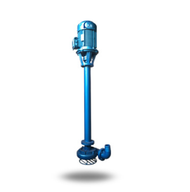
NL / NLA Vertical Slurry Sewage Pump is a vertical single-stage centrifugal pump designed for slurry, sewage, and sediment-containing liquid transfer in industrial and municipal systems.
It addresses clogging, sediment accumulation, and unstable discharge issues commonly encountered in solids-laden drainage applications.
It is used in construction site drainage, mining slurry transfer, municipal sewage pits, and industrial wastewater sumps.
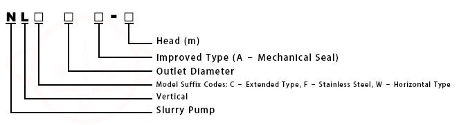
Model Designation
Applications
- Construction foundation pit drainage with sediment-laden water
- Mining slurry transfer with suspended particles
- Municipal sewage sump lifting with solids
- Industrial wastewater pits with sludge deposition
- Temporary dewatering systems with abrasive media
Engineering Advantages
The NL / NLA series adopts a vertical cantilever structure with single-stage centrifugal hydraulic design, allowing submerged suction intake while keeping the motor above liquid level to prevent contamination and simplify maintenance.
The open or semi-open impeller configuration enhances solids passage capability and reduces clogging risk in slurry and sewage service.
The rigid shaft support structure improves operational stability under variable slurry density conditions.
As described in the original engineering summary, the pump is suitable for vertical installation in pits and sumps handling slurry or sewage with suspended solids.
System Components
NL / NLA Vertical Slurry Sewage Pump mainly includes:
- Pump casing (volute)
- Impeller (open or semi-open type)
- Vertical shaft assembly
- Bearing housing
- Motor bracket and support frame
- Shaft seal structure
Technical Parameters
Service Conditions
- Installation in vertical sump or pit
- Ambient temperature ≤ 40°C
- Indoor or protected outdoor installation
Operating Conditions
Flow Rate: 20 – 180 m³/h
Head: 6 – 25 m
Power Range: 1.5 – 22 kW
Speed: 1450 rpm
Liquid Temperature: ≤ 80°C
Working Pressure: ≤ 0.6 MPa
Detailed parameter tables are provided below.
Installation & Dimensions
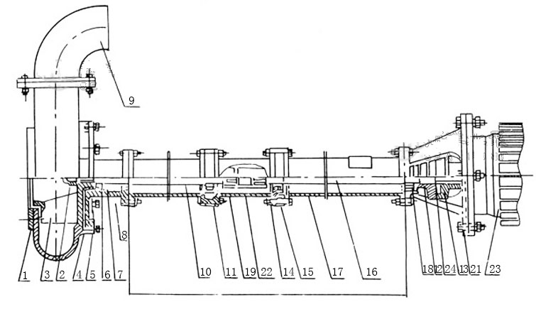
Outline Drawing
|
No.
|
Part Name / Type
|
No.
|
Part Name / Type
|
No.
|
Part Name / Type
|
|
1
|
Protective Screen
|
9
|
Discharge Elbow
|
17
|
Support Tube
|
|
2
|
Impeller Nut
|
10
|
Pump Shaft
|
18
|
Bearing Cover
|
|
3
|
Impeller
|
11
|
Bearing
|
19
|
Driven Coupling
|
|
4
|
Pump Casing
|
12
|
Driven Coupling
|
20
|
Motor Base
|
|
5
|
Pump Base
|
13
|
Driving Coupling
|
21
|
Motor Base C
|
|
6
|
O-ring
|
14
|
Connection Tube
|
22
|
Driving Coupling
|
|
7
|
Oil Seal
|
15
|
Bearing Seat
|
23
|
Motor
|
|
8
|
Shaft Sleeve
|
16
|
Connecting Shaft
|
24
|
Elastic Block
|
Performance Parameters
|
Model
|
Speed (rpm)
|
Flow Rate (m³/h)
|
Head (m)
|
Efficiency (%)
% |
Motor Power (kW)
|
Overall Height
mm |
Pump Weight (kg)
|
|
NL50-8
NL50A-8 |
1450
|
20-30
|
8-9
|
42
|
1.5
|
1310
|
63
|
|
NL50-12
NL50A-12 |
1450
|
25-38
|
12-14
|
41
|
3
|
1310
|
80
|
|
NL50-24
NL50A-24 |
1450
|
25-38
|
20-24
|
41
|
5.5
|
1430
|
152
|
|
NL65-16
NL65A-16 |
1450
|
50-60
|
15-18
|
42
|
5.5
|
1430
|
152
|
|
NL65-25
NL65A-25 |
1450
|
50-60
|
20-25
|
42
|
11
|
1510
|
265
|
|
NL76-9
NL76A-9 |
1450
|
50-70
|
9-10
|
42
|
3
|
1350
|
90
|
|
NL76-16
NL76A-16 |
1450
|
50-70
|
14-16
|
42
|
5.5
|
1430
|
152
|
|
NL76-20
NL76A-20 |
1450
|
50-70
|
18-20
|
42
|
7.5
|
1430
|
155
|
|
NL80-8
NL80A-8 |
1450
|
60-70
|
7-9
|
56
|
4
|
1400
|
120
|
|
NL80-12
NL80A-12 |
1450
|
80-120
|
11-13
|
56
|
7.5
|
1430
|
145
|
|
NL80-25
NL80A-25 |
1450
|
80-100
|
25
|
56
|
11
|
1550
|
270
|
|
NL100-7
NL100A-7 |
1450
|
70-80
|
6-8
|
61
|
4
|
1430
|
130
|
|
NL100-10
NL100A-10 |
1450
|
100
|
10
|
61
|
7.5
|
1450
|
160
|
|
NL100-16
NL100A-16 |
1450
|
80-100
|
15-17
|
61
|
15
|
1510
|
270
|
|
NL100-25
NL100A-25 |
1450
|
80-100
|
20-25
|
61
|
18.5
|
1690
|
350
|
|
NL150-12
NL150A-12 |
1450
|
100-150
|
11-13
|
66
|
18.5
|
1690
|
350
|
|
NL150-16
NL150A-16 |
1450
|
120-180
|
15-20
|
68
|
22
|
1690
|
370
|
How to Select a Pump Model
- Determine required flow rate and head based on drainage volume and lifting height.
- Evaluate solid particle size and slurry concentration to select appropriate impeller configuration.
- Confirm pit depth and shaft length to match installation height.
- Verify motor protection class and environmental conditions.
Engineering Notes
- Not suitable for long-distance high-pressure pipeline transport.
- Excessive solids concentration may accelerate wear of impeller and casing.
- Shaft rigidity must be considered for deep sump installation.
- Proper foundation support is required to minimize vibration.
Compliance & Quality Assurance
- Factory hydraulic performance testing
- Rotor dynamic balance inspection
- Hydrostatic pressure test of casing
- Material traceability documentation
- Optional third-party inspection
Safety Notice
- Do not operate under dry-running condition
- Ensure suction side remains submerged during operation
- Disconnect power before maintenance
- Do not exceed rated discharge pressure
OEM & Customization
This pump series supports engineered configuration and duty-based matching. Technical adjustments can be made according to system requirements and installation conditions.
Available options include:
• Motor voltage & frequency
• Mechanical seal type and configuration
• Wetted parts material selection
• Surface coating and corrosion protection
Configuration is determined based on duty point and project specifications.
FAQs
Q: Can the pump handle abrasive slurry?
A: Yes, within design concentration limits; excessive abrasion may require hardened material options.
Q: What is the allowable solid particle size?
A: It depends on impeller design and model selection; refer to technical data sheet.
Q: Can the pump operate under VFD control?
A: Yes, operation under VFD is permitted within rated hydraulic limits.
Q: What is the maximum allowable working pressure?
A: The maximum allowable working pressure is 0.6 MPa.
Q: What sealing options are available?
A: Mechanical seal or packing seal configurations are available depending on model.
Q: Is it suitable for continuous operation?
A: Yes, provided operation remains within specified duty range.