Product Overview
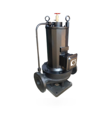
The PBG Vertical Canister-Mounted Inline Pump is a vertical centrifugal pipeline pump that integrates a shielded motor with the pump’s hydraulic system, designed for the continuous delivery of clean or similar liquids. The PBG series is developed based on advanced international technologies, complying with ISO 2858 and JB/T 6878.2-93 standards. It features a compact structure and stable operation, making it an ideal alternative to traditional horizontal centrifugal pumps and standard vertical inline pumps.
Model Designation

Key Features
-
Compact Structural Design
The compact design reduces installation space requirements, making it suitable for environments with space constraints, while simplifying installation and use. -
Integrated Pump and Motor Design
The integrated design ensures a tight connection between the pump and motor, optimizing space utilization, and ensuring stable operation with reduced installation complexity. -
Zero Leakage Performance
The advanced double-end mechanical seal system ensures the pump operates in a fully sealed state with zero leakage, enhancing reliability. -
Low Noise and Low Vibration
The optimized hydraulic design and sliding bearing arrangement effectively reduce vibration and noise levels, making it suitable for noise-sensitive environments. -
Easy Maintenance
The simplified design provides convenient maintenance operations, particularly in pump and motor maintenance and inspection, reducing downtime.
Engineering Overview
The PBG series pump uses advanced hydraulic design to ensure stable operation across the full head range. The compact and robust design is suitable for various flow and head requirements. The pump and motor are connected directly through a flexible coupling, eliminating the need for on-site alignment and simplifying the installation process. Under low flow conditions, the system automatically adjusts to ensure high efficiency.
Typical Applications
The PBG pump is widely used in the following fields:
-
Industrial and Municipal Water Supply Systems: Providing stable water supply to buildings, factories, and public facilities.
-
High-Rise Building Water Supply Systems: Ensuring reliable water pressure for multi-story buildings.
-
Firefighting Systems: Providing sufficient water sources for firefighting equipment.
-
Water Treatment and Recirculating Systems: For industrial and municipal water treatment applications.
System Configuration
The PBG series pump includes:
-
Pump Unit: Integrated with a shielded motor and hydraulic pump components, ensuring high efficiency and stable operation.
-
Automatic Control System: Intelligent pressure and flow regulation system for precise control.
-
Pressure Boosting Device: Ensures stable water pressure even under low flow conditions.
-
Pipeline and Connection Components: Made of corrosion-resistant materials, ensuring long-term stable operation.
Components & Supply
The main components of the PBG pump include:
-
Pump Body: Made from cast iron or stainless steel to ensure durability and corrosion resistance.
-
Impeller: High-efficiency design to ensure smooth fluid delivery.
-
Motor and Pump Connector: Flexible coupling between the pump and motor to reduce vibration.
-
Pressure Boosting Device: Maintains stable water pressure and compensates for any water pressure loss in the system.
Technical Service
The PBG series pump offers comprehensive technical support, including installation, commissioning, regular maintenance, and troubleshooting services, ensuring the efficient and reliable operation of the equipment.
Operating Conditions
-
Applicable Media: Clean liquids or similar non-corrosive media.
-
Flow Range: Select based on specific system requirements.
-
Temperature Range: Standard type for fluids up to 80°C; hot water type up to 160°C.
-
Pressure Range: System pressure ≤1.2 MPa.
Service Conditions
-
Regular Inspections: Regular checks of the pump unit, control system, pressure stabilization device, and pipelines to ensure safe and efficient operation.
-
Maintenance Requirements: Simple maintenance, mainly involving checking the impeller, bearings, and cooling system.
Protection Features
The PBG pump is equipped with overcurrent protection, temperature monitoring, and liquid level protection systems to ensure the system automatically stops in abnormal conditions to prevent equipment damage.
Selection Standards
When selecting the PBG pump, the following parameters should be considered:
-
Flow Rate Requirements: Select the appropriate pump model based on the design flow rate.
-
Head Requirements: Choose the pump based on the required pressure (head).
-
Medium Characteristics: Choose the pump model according to the corrosiveness, viscosity, and other properties of the medium.
Specifications & Installation
Outline Drawing

Performance Data
| No. | Name | No. | Name |
| 1 | Pump Body | 10 | Stator Shielding Sleeve |
| 2 | Seal Ring | 11 | Upper Bearing Seat |
| 3 | Impeller | 12 | Rotor End Cover |
| 4 | Lower Bearing Seat | 13 | Stator Shielding Sleeve |
| 5 | Motor Junction Box | 14 | Bearing |
| 6 | Motor Housing | 15 | Pump Cover |
| 7 | Bearing | 16 | Cooling Water Assembly |
| 8 | Stator Assembly | 17 | Shaft |
| 9 | Rotor Assembly |
Performance Curves

Performance Parameters
| Model | Diameter | Flow Rate | Head | Efficiency | Speed | Motor Power | Required NPSH | Weight | |
| mm | m³/h | L/s | m | % | r/min | kW | (NPSH)r | kg | |
| 20-110 | 20 |
1.8
2.5 3.3 |
0.5
0.69 0.91 |
16
15 13.5 |
25
34 35 |
2800 | 0.37 | 2.3 | 25 |
| 20-160 | 20 |
1.8
2.5 3.3 |
0.5
0.69 0.91 |
33
32 30 |
19
25 23 |
2900 | 0.75 | 2.3 | 29 |
| 25-110 | 25 |
2.8
4 5.2 |
0.78
1.11 1.44 |
16
15 13.5 |
34
42 41 |
2900 | 0.55 | 2.3 | 26 |
| 25-125 | 25 |
2.8
4 5.2 |
0.78
1.11 1.44 |
20.6
20 18 |
28
36 35 |
2900 | 0.75 | 2.3 | 28 |
| 25-125A | 25 |
2.5
3.6 4.6 |
0.69
1.0 1.28 |
17
16 14.4 |
35 | 2900 | 0.55 | 2.3 | 27 |
| 25-160 | 25 |
2.8
4 5.2 |
0.78
1.11 1.44 |
33
32 30 |
24
32 33 |
2900 | 1.5 | 2.3 | 39 |
| 25-160A | 25 |
2.6
3.7 4.9 |
0.12
1.03 1.36 |
29
28 26 |
31 | 2900 | 1.1 | 2.3 | 34 |
| 32-100 | 32 |
3.5
5 6.5 |
0.97
0.39 1.8 |
13.2
12.5 11.3 |
40
44 42 |
2900 | 0.75 | 2.3 | 28 |
| 32-125 | 32 |
3.5
5 6.5 |
0.97
0.39 1.8 |
22
20 18 |
40
44 42 |
2900 | 0.75 | 2.3 | 28 |
| 32-125A | 32 |
3.1
4.5 5.8 |
0.86
1.25 1.61 |
17.6
16 14.4 |
43 | 2900 | 0.75 | 2.3 | 28 |
| 32-160 | 32 |
3.5
5 6.5 |
0.97
0.39 1.8 |
33.2
32 30.2 |
48
54 53 |
2900 | 1.5 | 2.0 | 39 |
| 32-160A | 32 |
3.1
4.5 5.8 |
0.86
1.25 1.61 |
29
28 26.3 |
48
54 53 |
2900 | 1.1 | 2.0 | 39 |
| 32-200 | 32 |
3.5
5 6.5 |
0.97
0.39 1.8 |
50.5
50 48 |
34
40 42 |
2900 | 3 | 2.0 | 77 |
| 32-200A | 32 |
2.8
4 5.2 |
0.78
1.11 1.44 |
44.6
44 42.7 |
34
40 42 |
2900 | 2.2 | 2.0 | 74 |
| 32-100(I) | 32 |
4.4
6.3 8.3 |
1.22
1.75 2.32 |
13.2
12.5 11.3 |
48
54 53 |
2900 | 0.75 | 2.0 | 32 |
| 32-100(I)A | 32 |
4.4
6.3 8.3 |
1.22
1.75 2.32 |
13.2
12.5 11.3 |
48
54 53 |
2900 | 0.75 | 2.0 | 32 |
| 32-125(I) | 32 |
4.4
6.3 8.3 |
1.22
1.75 2.32 |
22
20 18 |
48
54 53 |
2900 | 1.1 | 2.3 | 34 |
| 32-125(I)A | 32 |
4.4
6.3 8.3 |
1.22
1.75 2.32 |
17.6
16 14.4 |
40
45 41 |
2900 | 0.75 | 2.3 | 33 |
| 32-160(I) | 32 |
4.4
6.3 8.3 |
1.22
1.75 2.32 |
33.2
32 30.2 |
34
40 42 |
2900 | 2.2 | 2.0 | 47 |
| 32-160(I)A | 32 |
4.1
5.9 7.8 |
1.14
1.64 2.17 |
29
28 26.3 |
34
39 39 |
2900 | 1.5 | 2.3 | 43 |
| 32-160(I)B | 32 |
3.8
5.5 7.2 |
1.06
1.53 2.0 |
25.5
24 22.5 |
34
38 37 |
2900 | 1.1 | 2.3 | 38 |
| 32-200(I) | 32 |
4.4
6.3 8.3 |
1.22
1.75 2.32 |
50.5
50 48 |
26
33 35 |
2900 | 4 | 2.0 | 43 |
| 32-200(I)A | 32 |
4.1
5.9 7.8 |
1.14
1.64 2.17 |
45
44 42 |
26
31 30 |
2900 | 3 | 2.3 | 62 |
| Model | Diameter | Flow Rate | Head | Efficiency | Speed | Motor Power | Required NPSH | Weight | |
| mm | m³/h | L/s | m | % | r/min | kW | (NPSH)r | kg | |
| 40-100 | 40 |
4.4
6.3 8.3 |
1.22
1.75 2.31 |
13.2
12.5 11.3 |
48
54 53 |
2900 | 0.55 | 2.3 | 32 |
| 40-100A | 40 |
3.9
5.6 7.4 |
1.08
1.56 2.06 |
10.6
10 9 |
52 | 2900 | 0.37 | 2.3 | 32 |
| 40-125 | 40 |
4.4
6.3 8.3 |
1.22
1.75 2.31 |
21
20 18 |
41
46 43 |
2900 | 1.1 | 2.3 | 34 |
| 40-125A | 40 |
3.9
5.6 7.4 |
1.08
1.56 2.06 |
17.6
16 14.4 |
40
45 41 |
2900 | 0.75 | 2.3 | 33 |
| 40-160 | 40 |
4.4
6.3 8.3 |
1.22
1.75 2.31 |
33
32 30 |
35
40 40 |
2900 | 2.2 | 2.3 | 47 |
| 40-160A | 40 |
4.1
5.9 7.8 |
1.14
1.64 2.17 |
29
28 26.3 |
34
39 39 |
2900 | 1.5 | 2.3 | 43 |
| 40-160B | 40 |
3.8
5.5 7.2 |
1.06
1.53 2.0 |
25.5
24 22.5 |
34
38 37 |
2900 | 1.1 | 2.3 | 38 |
| 40-200 | 40 |
4.4
6.3 8.3 |
1.22
1.75 2.31 |
51
50 48 |
26
33 32 |
2900 | 4 | 2.3 | 74 |
| 40-200A | 40 |
4.1
5.9 7.8 |
1.14
1.64 2.17 |
45
44 42 |
26
31 30 |
2900 | 3 | 2.3 | 62 |
| 40-200B | 40 |
3.7
5.3 7.0 |
1.03
1.47 1.94 |
38
36 34.5 |
29 | 2900 | 2.2 | 2.3 | 52 |
| 40-250 | 40 |
4.4
6.3 8.3 |
1.22
1.75 2.31 |
82
80 74 |
24
28 28 |
2900 | 7.5 | 2.3 | 105 |
| 40-250A | 40 |
4.1
5.9 7.8 |
1.14
1.64 2.17 |
72
70 65 |
24
28 27 |
2900 | 5.5 | 2.3 | 98 |
| 40-250B | 40 |
3.8
5.5 7.0 |
1.06
1.53 1.94 |
61.5
60 56 |
23
27 26 |
2900 | 4 | 2.3 | 77 |
| Model | Diameter | Flow Rate | Head | Efficiency | Speed | Motor Power | Required NPSH | Weight | |
| mm | m³/h | L/s | m | % | r/min | kW | (NPSH)r | kg | |
| 40-100(I) | 40 |
8.8
12.5 16.3 |
2.44
3.47 4.53 |
13.2
12.5 11.3 |
55
62 60 |
2900 | 1.1 | 2.3 | 34 |
| 40-100(I)A | 40 |
8
11 14.5 |
2.22
3.05 4.03 |
10.6
10 9 |
60 | 2900 | 0.75 | 2.3 | 32 |
| 40-125(I) | 40 |
8.8
12.5 16.3 |
2.44
3.47 4.53 |
21.2
20 17.8 |
49
58 57 |
2900 | 1.5 | 2.3 | 38 |
| 40-125(I)A | 40 |
8
11 14.5 |
2.22
3.05 4.03 |
17
16 14 |
57 | 2900 | 1.1 | 2.3 | 33 |
| 40-160(I) | 40 |
8.8
12.5 16.3 |
2.44
3.47 4.53 |
33
32 30 |
45
52 51 |
2900 | 3 | 2.3 | 56 |
| 40-160(I)A | 40 |
8.2
11.7 15.2 |
2.28
3.25 4.22 |
29
28 26 |
44
51 50 |
2900 | 2.2 | 2.3 | 47 |
| 40-160(I)B | 40 |
7.3
10.4 13.5 |
2.38
2.89 3.75 |
23
22 20.5 |
50 | 2900 | 1.5 | 2.3 | 43 |
| 40-200(I) | 40 |
8.8
12.5 16.3 |
2.44
3.47 4.53 |
51.2
50 48 |
38
46 46 |
2900 | 5.5 | 2.3 | 85 |
| 40-200(I)A | 40 |
8.3
11.7 15.3 |
2.31
3.25 4.25 |
45.0
44 42 |
37
45 45 |
2900 | 4 | 2.3 | 75 |
| 40-200(I)B | 40 |
7.5
10.6 13.8 |
2.08
2.94 3.83 |
37
36 34 |
44 | 2900 | 3 | 2.3 | 63 |
| 40-250(I) | 40 |
8.8
12.5 16.3 |
2.44
3.47 4.53 |
81.2
80 77.5 |
31
38 40 |
2900 | 11 | 2.3 | 145 |
| 40-250(I)A | 40 |
8.2
11.6 15.2 |
2.28
3.22 4.22 |
71.0
70 68 |
38 | 2900 | 7.5 | 2.3 | 95 |
| 40-250(I)B | 40 |
7.6
10.8 14 |
2.11
3.0 3.89 |
61.4
60 58 |
37 | 2900 | 7.5 | 2.3 | 94 |
| 40-250(I)C | 40 |
7.1
10.0 13.1 |
1.97
2.78 3.64 |
53.2
52 50.4 |
36 | 2900 | 5.5 | 2.3 | 88 |
| Model | Diameter | Flow Rate | Head | Efficiency | Speed | Motor Power | Required NPSH | Weight | |
| mm | m³/h | L/s | m | % | r/min | kW | (NPSH)r | kg | |
| 50-100 | 50 |
8.8
12.5 16.3 |
2.44
3.47 4.53 |
13.6
12.5 11.3 |
55
62 60 |
2900 | 1.1 | 2.3 | 36 |
| 50-100A | 50 |
8
11 14.5 |
2.22
3.05 4.03 |
11
10 9 |
60 | 2900 | 0.75 | 2.3 | 35 |
| 50-125 | 50 |
8.8
12.5 16.3 |
2.44
3.47 4.53 |
21.5
20 17.8 |
49
58 57 |
2900 | 1.5 | 2.3 | 43 |
| 50-125A | 50 |
8
11 14.5 |
2.22
3.05 4.03 |
17
16 14 |
57 | 2900 | 1.1 | 2.3 | 38 |
| 50-160 | 50 |
8.8
12.5 16.3 |
2.44
3.47 4.53 |
33
32 30 |
45
52 51 |
2900 | 3 | 2.3 | 59 |
| 50-160A | 50 |
8.2
11.7 15.2 |
2.28
3.25 4.22 |
29
28 26 |
44
51 50 |
2900 | 2.2 | 2.3 | 51 |
| 50-160B | 50 |
7.3
10.4 13.5 |
2.38
2.89 3.75 |
23
22 20.5 |
50 | 2900 | 1.5 | 2.3 | 47 |
| 50-200 | 50 |
8.8
12.5 16.3 |
2.44
3.47 4.53 |
52
50 48 |
38
46 46 |
2900 | 5.5 | 2.3 | 101 |
| 50-200A | 50 |
8.3
11.7 15.3 |
2.31
3.25 4.25 |
45.8
44 42 |
37
45 45 |
2900 | 4 | 2.3 | 80 |
| 50-200B | 50 |
7.5
10.6 13.8 |
2.08
2.94 3.83 |
37
36 34 |
44 | 2900 | 3 | 2.3 | 68 |
| 50-250 | 50 |
8.8
12.5 16.3 |
2.44
3.47 4.53 |
82
80 77.5 |
29
38 40 |
2900 | 11 | 2.3 | 160 |
| 50-250A | 50 |
8.2
11.6 15.2 |
2.28
3.22 4.22 |
71.5
70 68 |
38 | 2900 | 7.5 | 2.3 | 115 |
| 50-250B | 50 |
7.6
10.8 14 |
2.11
3.0 3.89 |
61.4
60 58 |
37 | 2900 | 7.5 | 2.3 | 114 |
| 50-250C | 50 |
7.1
10.0 13.1 |
1.97
2.78 3.64 |
53.2
52 50.4 |
36 | 2900 | 5.5 | 2.3 | 108 |
| Model | Diameter | Flow Rate | Head | Efficiency | Speed | Motor Power | Required NPSH | Weight | |
| mm | m³/h | L/s | m | % | r/min | kW | (NPSH)r | kg | |
| 50-100(I) | 50 |
17.5
25 32.5 |
4.86
6.94 9.03 |
13.7
12.5 10.5 |
67
69 69 |
2900 | 1.5 | 2.5 | 41 |
| 50-100(I)A | 50 |
15.6
22.3 29 |
4.3
6.19 8.1 |
11
10 8.4 |
65
67 68 |
2900 | 1.1 | 2.5 | 36 |
| 50-125(I) | 50 |
17.5
25 32.5 |
4.86
6.94 9.03 |
21.5
20 18 |
60
68 67 |
2900 | 3 | 2.5 | 56 |
| 50-125(I)A | 50 |
15.6
22.3 29 |
4.33
6.19 8.1 |
17
16 13.6 |
58
66 65 |
2900 | 2.2 | 2.5 | 48 |
| 50-160(I) | 50 |
17.5
25 32.5 |
4.68
6.94 9.03 |
34.4
32 27.5 |
54
63 60 |
2900 | 4 | 2.5 | 72 |
| 50-160(I)A | 50 |
16.4
23.4 30.4 |
4.56
6.5 8.44 |
30
28 24 |
54
62 59 |
2900 | 4 | 2.5 | 71 |
| 50-160(I)B | 50 |
15.0
21.6 28 |
4.17
6.0 7.78 |
26
24 20.6 |
58 | 2900 | 3 | 2.5 | 59 |
| 50-200(I) | 50 |
17.5
25 32.5 |
4.86
6.94 9.03 |
52.7
50 45.5 |
49
58 59 |
2900 | 7.5 | 2.5 | 108 |
| 50-200(I)A | 50 |
16.4
23.5 30.5 |
4.56
6.53 8.47 |
46.4
44 40 |
48
57 58 |
2900 | 7.5 | 2.5 | 107 |
| 50-200(I)B | 50 |
15.2
21.8 28.3 |
4.22
6.06 7.86 |
40
38 34.5 |
55 | 2900 | 5.5 | 2.5 | 100 |
| 50-250(I) | 50 |
17.5
25 32.5 |
4.86
6.94 9.03 |
82
80 76.5 |
39
50 52 |
2900 | 15 | 2.5 | 175 |
| 50-250(I)A | 50 |
16.4
23.4 30.5 |
4.56
6.5 8.47 |
71.5
70 67 |
39
50 52 |
2900 | 11 | 2.5 | 165 |
| 50-250(I)B | 50 |
15
21.6 28 |
4.17
6.0 7.78 |
61
60 57.4 |
38
49 54 |
2900 | 11 | 2.5 | 165 |
| 50-315(I) | 50 |
17.5
25 32.5 |
4.86
6.94 9.03 |
128
125 122 |
30
40 44 |
2900 | 30 | 2.5 | 310 |
| 50-315(I)A | 50 |
16.6
23.7 31 |
4.61
6.58 8.6 |
115
113 110 |
30
40 44 |
2900 | 22 | 2.5 | 245 |
| 50-315(I)B | 50 |
15.7
22.5 29.2 |
4.36
6.25 8.0 |
103
101 98 |
39 | 2900 | 18.5 | 2.5 | 215 |
| 50-315(I)C | 50 |
14.4
20.6 26.8 |
4.0
5.72 7.44 |
86
85 83 |
38 | 2900 | 15 | 2.5 | 195 |
| Model | Diameter | Flow Rate | Head | Efficiency | Speed | Motor Power | Required NPSH | Weight | |
| mm | m³/h | L/s | m | % | r/min | kW | (NPSH)r | kg | |
| 65-100 | 65 |
17.5
25 32.5 |
4.86
6.94 9.03 |
13.7
12.5 10.5 |
67
69 69 |
2900 | 1.5 | 2.5 | 46 |
| 65-100A | 65 |
15.6
22.3 29 |
4.3
6.19 8.1 |
11
10 8.4 |
65
67 68 |
2900 | 1.1 | 2.5 | 41 |
| 65-125 | 65 |
17.5
25 32.5 |
4.86
6.94 9.03 |
21.5
20 18 |
60
68 67 |
2900 | 3 | 2.5 | 58 |
| 65-125A | 65 |
15.6
22.3 29 |
4.33
6.19 8.1 |
17
16 14.4 |
58
66 65 |
2900 | 2.2 | 2.5 | 49 |
| 65-160 | 65 |
17.5
25 32.5 |
4.86
6.94 9.03 |
34.4
32 27.5 |
54
63 60 |
2900 | 4 | 2.5 | 75 |
| 65-160A | 65 |
16.4
23.4 30.4 |
4.56
6.5 8.44 |
30
28 24 |
54
62 59 |
2900 | 4 | 2.5 | 75 |
| 65-160B | 65 |
15.0
21.6 28 |
4.17
6.0 7.78 |
26
24 20.6 |
58 | 2900 | 3 | 2.5 | 63 |
| 65-200 | 65 |
17.5
25 32.5 |
4.86
6.94 9.03 |
52.7
50 45.5 |
49
58 59 |
2900 | 7.5 | 2.5 | 107 |
| 65-200A | 65 |
16.4
23.5 30.5 |
4.56
6.53 8.47 |
46.4
44 40 |
48
57 58 |
2900 | 7.5 | 2.5 | 107 |
| 65-200B | 65 |
15.2
21.8 28.3 |
4.22
6.06 7.86 |
40
38 34.5 |
55 | 2900 | 5.5 | 2.5 | 100 |
| 65-250 | 65 |
17.5
25 32.5 |
4.86
6.94 9.03 |
82
80 76.5 |
39
50 52 |
2900 | 15 | 2.5 | 180 |
| 65-250A | 65 |
16.4
23.4 30.5 |
4.56
6.5 8.47 |
71.5
70 67 |
39
50 52 |
2900 | 11 | 2.5 | 170 |
| 65-250B | 65 |
15
21.6 28 |
4.17
6.0 7.78 |
61
60 57.4 |
38
49 54 |
2900 | 11 | 2.5 | 170 |
| 65-315 | 65 |
17.5
25 32.5 |
4.86
6.94 9.03 |
127
125 122 |
32
40 44 |
2900 | 30 | 2.5 | 320 |
| 65-315A | 65 |
16.6
23.7 31 |
4.61
6.58 8.6 |
115
113 110 |
32
40 44 |
2900 | 22 | 2.5 | 255 |
| 65-315B | 65 |
15.7
22.5 29.2 |
4.36
6.25 8.0 |
103
101 98 |
39 | 2900 | 18.5 | 2.5 | 225 |
| 65-315C | 65 |
14.4
20.6 26.8 |
4.0
5.72 7.44 |
86
85 83 |
38 | 2900 | 15 | 2.5 | 205 |
| Model | Diameter | Flow Rate | Head | Efficiency | Speed | Motor Power | Required NPSH | Weight | |
| mm | m³/h | L/s | m | % | r/min | kW | (NPSH)r | kg | |
| 65-100(I) | 65 |
35
50 65 |
9.72
13.9 18.1 |
13.8
12.5 10 |
67
73 70 |
2900 | 3 | 3.0 | 63 |
| 65-100(I)A | 65 |
31.3
44.7 58 |
8.7
12.4 16.1 |
11
10 8 |
66
72 69 |
2900 | 2.2 | 3.0 | 53 |
| 65-125(I) | 65 |
35
50 65 |
9.72
13.9 18.1 |
22
20 17 |
67
72.5 70 |
2900 | 5.5 | 3.0 | 99 |
| 65-125(I)A | 65 |
31.3
44.7 58 |
8.7
12.5 16.1 |
17.5
16 13.6 |
66
71 69 |
2900 | 4 | 3.0 | 78 |
| 65-160(I) | 65 |
35
50 65 |
9.72
13.9 18.1 |
35
32 28 |
63
71 70 |
2900 | 7.5 | 3.0 | 103 |
| 65-160(I)A | 65 |
32.7
46.7 61 |
9.1
13.0 16.9 |
30.6
28 24 |
62
70 69 |
2900 | 7.5 | 3.0 | 103 |
| 65-160(I)B | 65 |
30.3
43.3 56.3 |
8.4
12.0 15.6 |
26
24 21 |
69 | 2900 | 5.5 | 3.0 | 97 |
| 65-200(I) | 65 |
35
50 65 |
9.72
13.9 18.1 |
53.5
50 46 |
55
67 68 |
2900 | 15 | 3.0 | 176 |
| 65-200(I)A | 65 |
32.8
47 61 |
9.1
13.1 16.9 |
47
44 40 |
54
66 67 |
2900 | 11 | 3.0 | 166 |
| 65-200(I)B | 65 |
30.5
43.5 56.6 |
8.5
12.1 15.7 |
40.6
38 33.4 |
65 | 2900 | 7.5 | 3.0 | 114 |
| 65-250(I) | 65 |
35
50 65 |
9.72
13.9 18.1 |
83
80 72 |
52
59 60 |
2900 | 22 | 3.0 | 235 |
| 65-250(I)A | 65 |
32.5
46.7 61 |
9.0
13.0 16.9 |
73
70 63 |
52
59 60 |
2900 | 18.5 | 3.0 | 205 |
| 65-250(I)B | 65 |
30
43.3 56 |
8.3
12.0 15.6 |
62
60 54 |
58 | 2900 | 15 | 3.0 | 180 |
| 65-315(I) | 65 |
35
50 65 |
9.72
13.9 18.1 |
128
125 121 |
44
54 57 |
2900 | 37 | 3.0 | 350 |
| 65-315(I)A | 65 |
32.5
46.5 60.5 |
9.0
12.9 16.8 |
112.6
110 106.4 |
43
54 57 |
2900 | 30 | 3.0 | 335 |
| 65-315(I)B | 65 |
31
44.5 58 |
8.6
12.4 16.1 |
102.5
100 98 |
53 | 2900 | 30 | 3.0 | 335 |
| 65-315(I)C | 65 |
29
41 53.6 |
8.1
11.4 14.9 |
87
85 83 |
51 | 2900 | 22 | 3.0 | 270 |
| Model | Diameter | Flow Rate | Head | Efficiency | Speed | Motor Power | Required NPSH | Weight | |
| mm | m³/h | L/s | m | % | r/min | kW | (NPSH)r | kg | |
| 80-100 | 80 |
35
50 65 |
9.72
13.9 18.1 |
13.8
12.5 10 |
67
73 70 |
2900 | 3 | 3.0 | 63 |
| 80-100A | 80 |
31.3
44.7 58 |
8.7
12.5 16.1 |
11
10 8 |
66
72 69 |
2900 | 2.2 | 3.0 | 54 |
| 80-125 | 80 |
35
50 65 |
9.72
13.9 18.1 |
22
20 17 |
67
72.5 70 |
2900 | 5.5 | 3.0 | 99 |
| 80-125A | 80 |
31.3
45 58 |
8.7
12.5 16.1 |
17.5
16 13.6 |
66
71 69 |
2900 | 4 | 3.0 | 79 |
| 80-160 | 80 |
35
50 65 |
9.72
13.9 18.1 |
35
32 28 |
63
71 70 |
2900 | 7.5 | 3.0 | 105 |
| 80-160A | 80 |
32.7
46.7 61 |
9.1
13.0 16.9 |
30.6
28 24 |
62
70 69 |
2900 | 7.5 | 3.0 | 105 |
| 80-160B | 80 |
30.3
43.3 56.3 |
8.4
12.0 15.6 |
26
24 21 |
69 | 2900 | 5.5 | 3.0 | 98 |
| 80-200 | 80 |
35
50 65 |
9.72
13.9 18.1 |
53.5
50 46 |
55
67 68 |
2900 | 15 | 3.0 | 175 |
| 80-200A | 80 |
32.8
47 61 |
9.1
13.1 16.9 |
47
44 40 |
54
66 67 |
2900 | 11 | 3.0 | 165 |
| 80-200B | 80 |
30.5
43.5 56.6 |
8.5
12.1 15.7 |
40.6
38 33.4 |
65 | 2900 | 7.5 | 3.0 | 115 |
| 80-250 | 80 |
35
50 65 |
9.72
13.9 18.1 |
83
80 72 |
52
59 60 |
2900 | 22 | 3.0 | 240 |
| 80-250A | 80 |
32.5
46.7 61 |
9.0
13.0 16.9 |
73
70 63 |
52
59 60 |
2900 | 18.5 | 3.0 | 210 |
| 80-250B | 80 |
30
43.3 56 |
8.3
12.0 15.6 |
62
60 54 |
58 | 2900 | 15 | 3.0 | 185 |
| 80-315 | 80 |
35
50 65 |
9.72
13.9 18.1 |
128
125 122 |
43
54 57 |
2900 | 37 | 3.0 | 355 |
| 80-315A | 80 |
32.5
46.5 60.5 |
9.0
12.9 16.8 |
112.6
110 107.4 |
43
54 57 |
2900 | 30 | 3.0 | 340 |
| 80-315B | 80 |
31
44.5 58 |
8.6
12.4 16.1 |
102.5
100 98 |
53 | 2900 | 30 | 3.0 | 340 |
| 80-315C | 80 |
29
41 53.6 |
8.1
11.4 14.9 |
98
85 83 |
51 | 2900 | 22 | 3.0 | 275 |
| 80-350 | 80 |
35
50 65 |
9.72
13.9 18.1 |
146
150 142 |
55
66 67 |
2900 | 55 | 3.0 | 570 |
| 80-350A | 80 |
31
44.5 58 |
8.6
12.4 16.1 |
138.4
142 134.8 |
65 | 2900 | 45 | 3.0 | 470 |
| 80-350B | 80 |
29
41 53.6 |
8.1
11.4 14.9 |
131.4
135 127.8 |
63 | 2900 | 37 | 3.0 | 440 |
| Model | Diameter | Flow Rate | Head | Efficiency | Speed | Motor Power | Required NPSH | Weight | |
| mm | m³/h | L/s | m | % | r/min | kW | (NPSH)r | kg | |
| 80-100(I) | 80 |
70
100 130 |
19.4
27.8 36.1 |
13.6
12.5 11 |
66
76 75 |
2900 | 5.5 | 4.5 | 108 |
| 80-100(I)A | 80 |
62.6
89 116 |
17.4
24.7 32.2 |
11
10 8.8 |
64
74 74 |
2900 | 4 | 4.5 | 87 |
| 80-125(I) | 80 |
70
100 130 |
19.4
27.8 36.1 |
23.5
20 14 |
70
76 65 |
2900 | 11 | 4.5 | 163 |
| 80-125(I)A | 80 |
62.6
89 116 |
17.4
24.7 32.2 |
19
16 11 |
68
74 65 |
2900 | 7.5 | 4.5 | 113 |
| 80-160(I) | 80 |
70
100 130 |
19.4
27.8 36.1 |
36.5
32 24 |
70
76 65 |
2900 | 15 | 4.5 | 184 |
| 80-160(I)A | 80 |
65.4
93.5 121.6 |
18.2
26.0 33.8 |
32
28 21 |
68
74 67 |
2900 | 11 | 4.5 | 174 |
| 80-160(I)B | 80 |
60.6
86.6 112.5 |
16.8
24.1 31.3 |
72
24 18 |
72 | 2900 | 11 | 4.5 | 174 |
| 80-200(I) | 80 |
70
100 130 |
19.4
27.8 36.1 |
54
50 42 |
65
74 73 |
2900 | 22 | 4.0 | 251 |
| 80-200(I)A | 80 |
65.4
93.5 121.6 |
18.2
26.0 33.8 |
47.5
44 37 |
64
73 72 |
2900 | 18.5 | 4.0 | 220 |
| 80-200(I)B | 80 |
61
87 113 |
16.9
24.2 31.4 |
41
38 32 |
71 | 2900 | 15 | 4.0 | 198 |
| 80-250(I) | 80 |
70
100 130 |
19.4
27.8 36.1 |
87
80 68 |
62
69 68 |
2900 | 37 | 4.0 | 330 |
| 80-250(I)A | 80 |
65.4
93.5 121.6 |
18.2
26.0 33.8 |
76
70 59.5 |
61
68 67 |
2900 | 30 | 4.0 | 315 |
| 80-250(I)B | 80 |
61
87 113 |
16.9
24.2 31.4 |
65
60 51 |
66 | 2900 | 30 | 4.0 | 315 |
| 80-315(I) | 80 |
70
100 130 |
19.4
27.8 36.1 |
132
125 114 |
55
66 67 |
2900 | 75 | 4.0 | 675 |
| 80-315(I)A | 80 |
66.5
95 123.6 |
18.5
26.4 34.3 |
119
113 103 |
55
66 67 |
2900 | 55 | 4.0 | 535 |
| 80-315(I)B | 80 |
63
90 117 |
17.5
25 32.5 |
106.6
101 92 |
65 | 2900 | 45 | 4.0 | 420 |
| 80-315(I)C | 80 |
58
82 107 |
16.1
22.8 29.7 |
90
85 76 |
63 | 2900 | 37 | 4.0 | 366 |
| Model | Diameter | Flow Rate | Head | Efficiency | Speed | Motor Power | Required NPSH | Weight | |
| mm | m³/h | L/s | m | % | r/min | kW | (NPSH)r | kg | |
| 100-100 | 100 |
70
100 130 |
19.4
27.8 36.1 |
13.6
12.5 11 |
66
76 75 |
2900 | 5.5 | 4.5 | 113 |
| 100-100A | 100 |
62.6
89 116 |
17.4
47 32.2 |
11
10 8.8 |
64
74 74 |
2900 | 4 | 4.5 | 91 |
| 100-125 | 100 |
70
100 130 |
19.4
27.8 36.1 |
23.5
20 14 |
70
76 65 |
2900 | 11 | 4.5 | 169 |
| 100-125A | 100 |
62.6
89 116 |
17.4
24.7 32.2 |
19
16 11 |
68
74 63 |
2900 | 7.5 | 4.5 | 118 |
| 100-160 | 100 |
70
100 130 |
19.4
27.8 36.1 |
36.5
32 24 |
70
76 65 |
2900 | 15 | 4.5 | 191 |
| 100-160A | 100 |
65.4
93.5 121.6 |
18.2
26.0 33.8 |
32
28 21 |
68
74 67 |
2900 | 11 | 4.5 | 181 |
| 100-160B | 100 |
60.6
86.6 112.5 |
16.8
24.1 31.3 |
27
24 18 |
72 | 2900 | 11 | 4.5 | 181 |
| 100-200 | 100 |
70
100 130 |
19.4
27.8 36.1 |
54
50 42 |
65
74 73 |
2900 | 22 | 4.0 | 245 |
| 100-200A | 100 |
65.4
93.5 121.6 |
18.2
26.0 33.8 |
47.5
44 37 |
64
73 72 |
2900 | 18.5 | 4.0 | 215 |
| 100-200B | 100 |
61
87 113 |
16.9
24.2 31.4 |
41
38 32 |
71 | 2900 | 15 | 4.0 | 193 |
| 100-250 | 100 |
70
100 130 |
19.4
27.8 36.1 |
37
80 68 |
62
69 68 |
2900 | 37 | 4.0 | 345 |
| 100-250A | 100 |
65.4
93.5 121.6 |
18.2
26.0 33.8 |
76
70 59.5 |
61
68 67 |
2900 | 30 | 4.0 | 330 |
| 100-250B | 100 |
61
87 113 |
16.9
24.2 31.4 |
65
60 51 |
66 | 2900 | 30 | 4.0 | 330 |
| 100-315 | 100 |
70
100 130 |
19.4
27.8 36.1 |
132
125 114 |
55
66 67 |
2900 | 75 | 4.0 | 689 |
| 100-315A | 100 |
66.5
95 123.6 |
18.5
26.4 34.3 |
119
113 103 |
65
66 67 |
2900 | 55 | 4.0 | 549 |
| 100-315B | 100 |
63
90 117 |
17.5
25 32.5 |
106.6
101 92 |
65 | 2900 | 45 | 4.0 | 439 |
| 100-315C | 100 |
58
82 107 |
16.1
22.8 29.7 |
90
85 76 |
63 | 2900 | 37 | 4.0 | 385 |
| Model | Diameter | Flow Rate | Head | Efficiency | Speed | Motor Power | Required NPSH | Weight | |
| mm | m³/h | L/s | m | % | r/min | kW | (NPSH)r | kg | |
| 100-100(I) | 100 |
96
160 192 |
26.7
44.4 53.3 |
14
12.5 10 |
64
73 70 |
2900 | 11 | 4.5 | 115 |
| 100-125(I) | 100 |
96
160 192 |
26.7
44.4 53.3 |
24
20 14 |
62
74 69 |
2900 | 15 | 4.5 | 168 |
| 100-125(I)A | 100 |
84
140 168 |
23.3
39 46.7 |
20
17 12 |
64
72 68 |
2900 | 11 | 4.5 | 168 |
| 100-160(I) | 100 |
96
160 192 |
26.7
44.4 53.3 |
36
32 27 |
69
79 75 |
2900 | 22 | 5.6 | 210 |
| 100-160(I)A | 100 |
84
140 168 |
23.3
39 46.7 |
32
28 23.5 |
66
76 72 |
2900 | 18.5 | 5.0 | 210 |
| 100-200(I) | 100 |
96
160 192 |
26.7
44.4 53.3 |
53
50 45 |
69
79 78 |
2900 | 37 | 5.2 | 402 |
| 100-200(I)A | 100 |
84
140 168 |
23.3
39 46.7 |
48
45 40 |
64
74 73 |
2900 | 30 | 4.5 | 395 |
| 100-200(I)B | 100 |
60
100 120 |
16.7
27.8 33.3 |
43
40 36 |
72 | 2900 | 22 | 4.5 | 360 |
| 100-250(I) | 100 |
96
160 192 |
26.7
44.4 53.3 |
83
80 72 |
65
77 74 |
2900 | 55 | 4.8 | 560 |
| 100-250(I)A | 100 |
84
140 168 |
23.3
39 46.7 |
75
72 65 |
60
72 69 |
2900 | 45 | 4.5 | 420 |
| 100-250(I)B | 100 |
60
100 120 |
16.7
27.8 33.3 |
68
65 58 |
70 | 2900 | 37 | 4.5 | 400 |
| 100-350 | 100 |
60
100 120 |
16.7
27.8 33.3 |
153.6
150 142 |
72
57 74 |
2900 | 90 | 4.0 | 950 |
| 100-350A | 100 |
61
87 113 |
16.9
24.2 31.4 |
145.6
142 134 |
75 | 2900 | 75 | 4.0 | 830 |
| 100-350B | 100 |
58
82 107 |
16.1
22.8 29.7 |
138.6
135 127 |
75 | 2900 | 55 | 4.0 | 600 |
| Model | Diameter | Flow Rate | Head | Efficiency | Speed | Motor Power | Required NPSH | Weight | |
| mm | m³/h | L/s | m | % | r/min | kW | (NPSH)r | kg | |
| 125-100 | 125 |
96
160 192 |
26.7
44.4 53.3 |
13
12.5 12 |
82 | 2900 | 11 | 4.0 | 180 |
| 125-100A | 125 |
86
143 172 |
23.9
39.7 47.8 |
10.4
10 9.6 |
77 | 2900 | 7.5 | 4.0 | 125 |
| 125-125 | 125 |
96
160 192 |
26.7
44.4 53.3 |
22.6
20 17 |
80 | 2900 | 15 | 4.0 | 220 |
| 125-125A | 125 |
86
143 172 |
23.9
39.7 47.8 |
18
16 13.6 |
77 | 2900 | 11 | 4.0 | 210 |
| 125-160 | 125 |
96
160 192 |
26.7
44.4 53.3 |
36
32 28 |
78 | 2900 | 22 | 4.0 | 265 |
| 125-160A | 125 |
90
150 180 |
25
41.7 50 |
31.5
28 24.5 |
76 | 2900 | 18.5 | 4.0 | 230 |
| 125-160B | 125 |
83
138 166 |
21.7
38.3 46.1 |
27
24 21 |
73 | 2900 | 15 | 4.0 | 215 |
| 125-200 | 125 |
96
160 192 |
26.7
44.4 53.3 |
55
50 46 |
77 | 2900 | 37 | 5.5 | 395 |
| 125-200A | 125 |
90
150 180 |
25
41.7 50 |
48.4
44 40.5 |
76 | 2900 | 30 | 5.5 | 380 |
| 125-200B | 125 |
83
138 166 |
21.7
38.3 46.1 |
41.3
37.5 34.5 |
75 | 2900 | 22 | 5.5 | 320 |
| 125-250 | 125 |
96
160 192 |
26.7
44.4 53.3 |
87
80 73 |
75 | 2900 | 55 | 5.0 | 580 |
| 125-250A | 125 |
90
150 180 |
25
41.7 50 |
76
70 84 |
74 | 2900 | 45 | 5.5 | 490 |
| 125-250B | 125 |
83
138 166 |
21.7
38.3 46.1 |
65
60 55 |
73 | 2900 | 37 | 5.5 | 430 |
| 125-315 | 125 |
96
160 192 |
26.7
44.7 53.3 |
133
125 119 |
70 | 2900 | 90 | 5.0 | 790 |
| 125-315A | 125 |
90
150 180 |
25
41.7 50 |
117
110 104.6 |
70 | 2900 | 75 | 5.0 | 710 |
| 125-315B | 125 |
86
143 172 |
23.9
39.7 47.8 |
106.4
100 95.2 |
69 | 2900 | 75 | 5.0 | 705 |
| 125-315C | 125 |
80.5
134 161 |
22.4
37.2 44.7 |
96
88 86 |
67 | 2900 | 55 | 5.0 | 585 |
| Model | Diameter | Flow Rate | Head | Efficiency | Speed | Motor Power | Required NPSH | Weight | |
| mm | m³/h | L/s | m | % | r/min | kW | (NPSH)r | kg | |
| 150-125 | 150 |
96
160 192 |
26.7
44.4 53.3 |
22.6
24 17 |
66
76 76 |
2900 | 11 | 4.0 | 210 |
| 150-125A | 150 |
90
150 180 |
25
41.7 50 |
18
16 13.6 |
77 | 2900 | 7.5 | 4.0 | 130 |
| 150-160 | 150 |
96
160 192 |
26.7
44.4 53.3 |
36
32 27 |
75 | 2900 | 22 | 4.0 | 270 |
| 150-160A | 150 |
90
150 180 |
25
41.7 50 |
32
28 23.5 |
76 | 2900 | 18.5 | 4.0 | 230 |
| 150-160B | 150 |
84
140 168 |
23.3
39 46.7 |
27
24 21 |
73 | 2900 | 15 | 4.0 | 220 |
| 150-200 | 150 |
96
160 192 |
26.7
44.4 53.3 |
55
50 46 |
77 | 2900 | 37 | 5.5 | 395 |
| 150-200A | 150 |
90
150 180 |
25
41.7 50 |
48.4
44 40.5 |
76 | 2900 | 30 | 5.5 | 380 |
| 150-200B | 150 |
84
140 168 |
23.3
39 46.7 |
41
38 34 |
75 | 2900 | 22 | 4.0 | 275 |
| 150-250 | 150 |
140
200 260 |
38.9
55.6 72.2 |
87
80 73 |
75 | 2900 | 75 | 5.0 | 630 |
| 150-250A | 150 |
131
187 243 |
36.4
51.9 67.5 |
76
70 84 |
74 | 2900 | 55 | 5.5 | 530 |
| 150-250B | 150 |
121
173 225 |
33.5
48.1 62.5 |
65
60 55 |
73 | 2900 | 45 | 5.5 | 480 |
| 150-315 | 150 |
140
200 260 |
38.9
55.6 72.2 |
133
125 119 |
70 | 2900 | 110 | 5.0 | 1080 |
| 150-315A | 150 |
131
187 243 |
36.4
51.9 67.5 |
117
110 104.6 |
70 | 2900 | 90 | 5.0 | 820 |
| 150-315B | 150 |
121
173 225 |
33.5
48.1 62.5 |
106.4
100 95.2 |
69 | 2900 | 75 | 5.0 | 770 |
| 150-315C | 150 |
112
160 208 |
31.3
44.4 57.8 |
96
88 86 |
67 | 2900 | 55 | 5.0 | 640 |
| 150-350 | 150 |
96
160 192 |
26.7
44.4 53.3 |
153.6
150 142.8 |
80 | 2900 | 110 | 5.5 | 970 |
| 150-350A | 150 |
90
150 180 |
25
41.7 50 |
145.6
142 134.8 |
70 | 2900 | 90 | 5.2 | 790 |
| 150-350B | 150 |
84
140 168 |
23.3
39 46.7 |
138.6
135 127.8 |
65
76 74 |
2900 | 75 | 5.5 | 705 |
Operating Manual
Installation Instructions
- Before installation, check whether all fasteners of the pump unit are tightened and ensure the pump chamber is free of foreign objects to avoid impeller or pump body damage during operation.
- The weight of the pipeline must not be supported by the pump. Each pipeline section should have its own support to prevent pump deformation, which may affect performance and service life.
- To prevent impurities from entering the pump and blocking the flow passage, install a filter in front of the pump inlet. The filter area should be 3–4 times larger than the suction pipe cross-sectional area.
- When pumping hot liquids, to avoid thermal deformation transmitted from the pipeline to the pump, the pump base bolts may remain unfixed so that the pump can move together with the pipeline during thermal expansion and contraction.
- For easy maintenance and safe operation, install regulating valves and pressure gauges at both the inlet and outlet of the pump to ensure operation within the rated performance range.
Maintenance and Service
1. Preparation Before Startup
- Check whether the grounding of the canned motor and starting equipment is complete and reliable, and whether all wiring connections are correct.
- For newly installed or long-idle canned motors, check the insulation resistance of the stator windings to ground before use.
- The pipeline must be completely filled with liquid; otherwise, the motor service life will be affected.
2. Maintenance During Operation
- Record the voltage regularly, including variations and unbalance. Overvoltage, undervoltage, or voltage unbalance may cause motor overheating and abnormal operation.
- Record the pump load current and current unbalance regularly. Most pump failures manifest as abnormally high stator current, causing the motor to overheat.
- Record the liquid temperature in the pipeline frequently to ensure it does not exceed the rated temperature on the nameplate, preventing long-term overheating.
- Record inlet and outlet pressure gauge readings. The inlet pressure must not be lower than zero, and the pressure difference between outlet and inlet must meet rated values.
- Before each use, exhaust air from the pump. During long-term operation, the pump must be vented once every week.
- Monitor odors, vibration, and noise during operation. Overheated motor windings produce a burnt-insulation smell. Mechanical faults typically manifest as abnormal vibration or noise. Stop the pump immediately if abnormalities are detected.
- Check the circulation path and filter of the cooling liquid regularly to ensure that no blockage occurs.
- Periodically measure the clearance between the graphite bearing and the shaft sleeve to keep the gap uniform between the stator and rotor shielding sleeves. Exceeding the limits requires repair or replacement.
Allowable Bearing Clearance
| Sleeve Diameter (mm) | Wear Limit Clearance (mm) | Standard Clearance (mm) |
| >18–30 | 0.40 | 0.131 |
| >30–50 | 0.45 | 0.158 |
| >50–80 | 0.50 | 0.192 |
9. Regularly check the clearance between the impeller wear ring and pump body. Excessive clearance affects pump performance. If the clearance exceeds 1.5 mm, replace the impeller. Under special conditions, repair techniques may be applied.
Operation & Running
1. Startup and Operation
- Fill the pump completely with liquid and exhaust air. Open the inlet valve and loosen the vent valve on the top of the motor. Close the vent valve after air is fully discharged.
- Close the outlet valve to reduce starting current.
- Check all components to ensure they are functioning normally.
- Switch on the power supply and confirm the correct rotation direction.
- Gradually open the outlet valve to bring the pump to operation within the rated performance range.
- If any abnormalities occur during operation, stop the pump immediately for inspection.
- Check the motor current and temperature rise to ensure they comply with rated requirements.
2. Shutdown
- Close the discharge valve.
- Cut off power to stop the motor.
- Close the inlet valve.
- If the pump remains out of service for a long time, drain all liquid from the pump.
OEM & Custom
Chaodun Pump provides OEM and ODM customization including brand labeling, stainless-steel upgrades, explosion-proof or variable-speed motor options, and system integration for HVAC and industrial use. Export packaging and design modifications are supported.
FAQs
- 1. What is the PBG canned motor pump used for?
It is designed for clean water and HVAC circulation in buildings and industrial systems. - 2. What temperature can it handle?
The standard model supports up to 80°C, and the hot water version up to 160°C. - 3. Is it completely leak-free?
Yes. The motor and pump are integrated with a sealed stainless-steel sleeve structure. - 4. Can it be used for chemical or corrosive liquids?
Yes, the anti-corrosive model handles liquids similar to water in viscosity. - 5. What maintenance is required?
Only periodic cleaning and inspection of bearings and cooling channels. - 6. Does it make noise during operation?
No, the pump is extremely quiet and vibration-free due to its sealed motor design. - 7. Can Chaodun Pump customize OEM models?
Yes, Chaodun Pump supports OEM production, logo customization, and export-specific configurations.