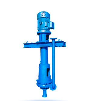
PN/PNL Mud Pump – Horizontal & Vertical Single Stage Slurry Pump
PN/PNL Mud Pump (H/V) | Single-stage slurry transfer
- Slurry duty: Solids-laden mud handling.
- Wear-resistant wet end: Replaceable wear parts.
- H/V options: Layout flexibility.
- Easy service: Straightforward maintenance.