Product Overview
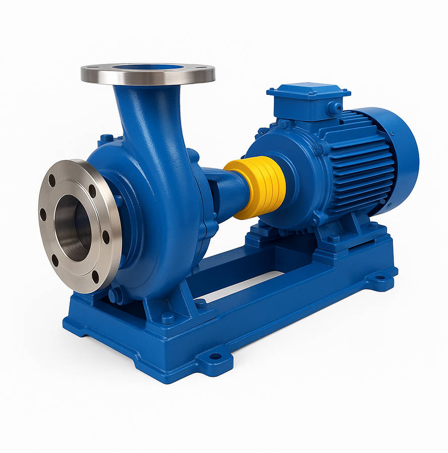
PW / PWF Horizontal Sewage Pump is a single-stage, single-suction horizontal centrifugal pump designed for large-flow low-head sewage transfer in municipal and industrial drainage systems.
It addresses open-channel intake, high-flow wastewater movement, and stable operation under non-clogging drainage conditions.
It is suitable for municipal sewage stations, river water lifting, irrigation drainage, industrial wastewater discharge, and large-area surface water removal.
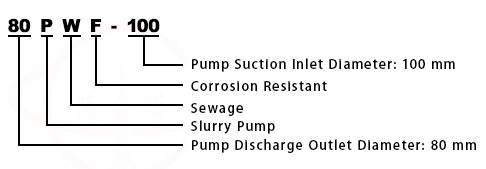
Model Meaning
Applications
Typical Operating Conditions
• Municipal sewage lifting stations
• River and canal water diversion
• Agricultural irrigation and drainage
• Industrial wastewater transfer
• Flood control and surface water removal
Engineering Advantages
• Single-stage large-channel impeller improves solid passage capability
• Horizontal structure allows convenient maintenance and alignment
• Cast iron casing with optimized hydraulic passage reduces flow resistance
• External bearing support enhances shaft rigidity and durability
• Designed for open intake or flooded suction installation conditions
System Components
PW / PWF Horizontal Sewage Pump:
The PW / PWF Horizontal Sewage Pump mainly consists of:
• Pump casing
• Single-stage impeller
• Pump shaft
• Shaft sleeve
• Bearing assembly
• Mechanical or packing seal
• Coupling and base frame
Technical Specifications
Service Conditions
• Medium: Sewage containing suspended solids
• Installation: Horizontal base-mounted configuration
• Suitable for open or flooded suction systems
Operating Conditions
Flow rate: 14.5– 1000 m³/h
Head: 9.5 – 43 m
Power range: 4 – 132 kW
Speed: 730 rpm/ 960 rpm/ 980rpm/ 1440rpm/ 2900rpm
Liquid temperature: ≤ 80°C
Working pressure: ≤ 0.6 MPa
Detailed parameter tables are provided below.
Installation & Dimensions
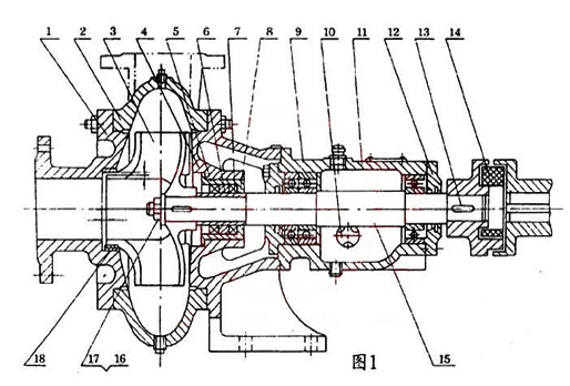
Outline Drawing
Performance Data
|
No.
|
Name
|
No.
|
Name
|
|
1
|
Pump Cover
|
10
|
Oil Indicator
|
|
2
|
Pump Body
|
11
|
Bearing Housing
|
|
3
|
Impeller
|
12
|
Bearing Cover
|
|
4
|
Seal Body
|
13
|
Flat Key
|
|
5
|
Seal Box
|
14
|
Elastic Ring
|
|
6
|
Washer
|
15
|
Shaft
|
|
7
|
Shaft Sleeve (Not used in 4PW)
|
16
|
Nut
|
|
8
|
Oil Seal
|
17
|
Gasket
|
|
9
|
Bearing
|
18
|
Seal Ring
|
Performance Parameters
|
Item No.
|
Model
|
Flow Rate (m³/h)
|
Head (m)
|
Speed (rpm)
|
Power (kW)
|
||
|
m3/h
|
L/s
|
m
|
r/min
|
Shaft Power
|
Power (kW)
|
||
|
1
|
50PW-65
50PWF-65 |
14.5
|
4
|
16
|
1440
|
2.47
|
4
|
|
2
|
50PW-65
50PWF-65 |
25
|
6.94
|
32
|
2900
|
3.35
|
4
|
|
3
|
80PW-100
80PWF-100 |
56
|
15.5
|
13.5
|
1440
|
4.1
|
5.5
|
|
4
|
80PW-100
80PWF-100 |
90
|
25
|
26
|
2900
|
7
|
11
|
|
5
|
100PW-125
100PWF-125 |
100
|
27.8
|
12.5
|
1440
|
5.7
|
7.5
|
|
6
|
21/2PW
|
60
|
16.6
|
9.5
|
1440
|
2.5
|
4
|
|
7
|
21/2PW
|
90
|
25
|
26
|
2920
|
11
|
15
|
|
8
|
21/2PW
|
90
|
25
|
43
|
2940
|
17
|
22
|
|
9
|
4PW
|
100
|
27.8
|
11
|
960
|
4.7
|
7.5
|
|
10
|
4PW
|
160
|
44.4
|
25.5
|
1460
|
18
|
30
|
|
11
|
6PW
|
300
|
83.3
|
14
|
980
|
17
|
30
|
|
12
|
6PW
|
350
|
97
|
27
|
1450
|
42
|
55
|
|
13
|
8PW
|
500
|
139
|
13
|
730
|
29
|
45
|
|
14
|
8PW
|
550
|
153
|
25
|
980
|
59.5
|
75
|
|
15
|
10PW
|
800
|
222
|
13.5
|
730
|
40.2
|
75
|
|
16
|
10PW
|
1000
|
278
|
25
|
980
|
92
|
132
|
How to Select a Pump Model
• Determine required discharge flow and system head
• Evaluate solid particle size and concentration
• Confirm suction condition (open channel or flooded)
• Select appropriate sealing type (mechanical or packing)
• Verify motor power and installation base requirements
Engineering Notes
• Not suitable for highly abrasive slurry
• Excessive fibrous materials may affect impeller performance
• Ensure stable foundation to prevent misalignment
• Long suction pipelines require check valves and air release devices
• Operate within rated hydraulic limits
Compliance & Quality Assurance
• Factory hydraulic performance testing
• Casing hydrostatic pressure testing
• Rotor dynamic balance inspection
• Bearing clearance verification
• Material traceability documentation
• Optional third-party inspection available
Safety Notice
• Do not operate under dry-running condition
• Ensure suction system is fully primed before startup
• Do not exceed rated discharge pressure
• Disconnect power before maintenance
OEM & Customization
This pump series supports engineered configuration and duty-based matching. Technical adjustments can be made according to system requirements and installation conditions.
Available options include:
• Motor voltage & frequency
• Mechanical or packing seal configuration
• Impeller material selection
• Surface coating protection
• Base frame customization
Configuration is determined based on duty point and project specifications.
FAQs
Q: Can the pump operate under VFD control?
A: Yes, within rated motor load and hydraulic limits.
Q: What is the maximum allowable solid size?
A: It depends on the impeller passage design and specific model.
Q: What sealing options are available?
A: Mechanical seal or packing seal configurations.
Q: What is the maximum allowable working pressure?
A: ≤ 0.6 MPa under rated conditions.
Q: What rotational speed is standard?
A: 1450 rpm.
Q: Is it suitable for open-channel suction?
A: Yes, it is designed for open or flooded suction systems.
Q: What type of medium is permitted?
A: Sewage containing suspended solids without excessive abrasiveness.