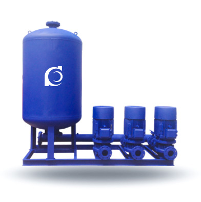
Product Overview
QHYB-ISG Variable Frequency Water Supply System (ISG) is an integrated water supply solution that combines ISG single-stage vertical centrifugal pumps with variable frequency drive (VFD), pressure sensor feedback, and PLC intelligent control for efficient and automated water regulation.
It addresses the issues of unstable pressure during varying demand conditions, energy inefficiency with constant-speed pumps, and manual operation requirements in traditional systems.
It is ideal for residential buildings, commercial complexes, industrial water supply systems, and municipal water distribution networks requiring constant pressure and energy-efficient operation.
Model Designation

Applications
• High-rise building water supply systems
• Residential community water distribution networks
• Commercial and industrial water supply systems
• Municipal secondary water supply systems
• Automated water supply control for various commercial and residential applications
Engineering Advantages
• VFD control optimizes energy usage by adjusting pump speed to match varying demand, reducing electricity consumption.
• PLC intelligent control system provides automated operation, eliminating the need for manual intervention and improving operational efficiency.
• ISG vertical centrifugal pumps provide stable, reliable performance with high efficiency, making them ideal for demanding water supply systems.
• Integrated pressure sensor feedback ensures precise pressure regulation and consistent water supply, even during fluctuating demand.
• Compact and space-saving design allows for easy integration into existing water distribution systems, saving installation space.
System Components
The QHYB-ISG Variable Frequency Water Supply System consists of the following main components:
• ISG vertical centrifugal pump units
• Variable frequency drive (VFD) control system
• PLC intelligent control cabinet
• Pressure sensor feedback system
• Inlet and outlet valves
• Anti-vibration base and mounting frame
Technical Parameters
Service Conditions
Clean water without solid particles or fibers
Non-corrosive or mildly corrosive liquid media
Indoor installation
Operating Conditions
Flow rate: 10 – 200 m³/h
Head: 20 – 150 m
Power range: 2.2 – 75 kW
Speed: 2900 rpm
Liquid temperature: ≤ 80°C
Working pressure: ≤ 1.6 MPa
Detailed parameter tables are provided below.
Performance Parameters
| Applicable Buildings | Sprinkler Flow (L/s) | Sprinkler Operating Pressure (MPa) | Applicable Building Height (m) | Recommended Water Supply System Model (Vertical Pump Set) | ||
| Building Type | Design Sprinkler Density (L/(min·m²)) | Coverage Area (m²) | ||||
| Industrial Building | 10 | 300 | 60 | 0.1 | ≤12 | QHYB60-0.24-100ISG-3 |
| Industrial Building | 10 | 300 | 60 | 0.1 | ≤24 | QHYB60-0.4-100ISG-3 |
| Industrial Building | 10 | 300 | 60 | 0.1 | ≤36 | QHYB60-0.6-100ISG-3 |
| Industrial Building | 10 | 300 | 60 | 0.1 | ≤50 | QHYB60-0.8-100ISG-3 |
| Industrial Building | 10 | 300 | 60 | 0.1 | ≤72 | QHYB60-1.0-100ISG-3 |
| Industrial Building | 10 | 300 | 60 | 0.1 | ≤100 | QHYB60-1.2-100ISG-3 |
| Storage Building | 15 | 300 | 90 | 0.1 | ≤12 | QHYB90-0.24-150ISG-3 |
| Storage Building | 15 | 300 | 90 | 0.1 | ≤24 | QHYB90-0.4-150ISG-3 |
| Storage Building | 15 | 300 | 90 | 0.1 | ≤36 | QHYB90-0.6-150ISG-3 |
| Storage Building | 15 | 300 | 90 | 0.1 | ≤50 | QHYB90-0.8-150ISG-3 |
| Storage Building | 15 | 300 | 90 | 0.1 | ≤72 | QHYB90-1.0-150ISG-3 |
| Storage Building | 15 | 300 | 90 | 0.1 | ≤100 | QHYB90-1.2-150ISG-3 |
| Ordinary Hazard | 6 | 300 | 40 | 0.1 | ≤12 | QHYB40-0.24-100ISG-3 |
| Ordinary Hazard | 6 | 300 | 40 | 0.1 | ≤24 | QHYB40-0.4-100ISG-3 |
| Ordinary Hazard | 6 | 300 | 40 | 0.1 | ≤36 | QHYB40-0.6-100ISG-3 |
| Ordinary Hazard | 6 | 300 | 40 | 0.1 | ≤50 | QHYB40-0.8-100ISG-3 |
| Ordinary Hazard | 6 | 300 | 40 | 0.1 | ≤72 | QHYB40-1.0-100ISG-3 |
| Ordinary Hazard | 6 | 300 | 40 | 0.1 | ≤100 | QHYB40-1.2-100ISG-3 |
| Light Hazard | 3 | 300 | 15 | 0.1 | ≤12 | QHYB15-0.24-65ISG-3 |
| Light Hazard | 3 | 300 | 15 | 0.1 | ≤24 | QHYB15-0.4-65ISG-3 |
| Light Hazard | 3 | 300 | 15 | 0.1 | ≤36 | QHYB15-0.6-65ISG-3 |
| Light Hazard | 3 | 300 | 15 | 0.1 | ≤50 | QHYB15-0.8-65ISG-3 |
| Light Hazard | 3 | 300 | 15 | 0.1 | ≤72 | QHYB15-1.0-65ISG-3 |
| Light Hazard | 3 | 300 | 15 | 0.1 | ≤100 | QHYB15-1.2-65ISG-3 |
| Users can select the appropriate model according to the parameters provided. | ||||||
How to Select a Pump Model
• Define the system’s peak flow rate and daily water consumption profile
• Calculate the total head, including elevation and pipeline resistance
• Choose the number of pumps and configuration type based on system redundancy requirements
• Determine the required control features, such as automated pressure regulation and system integration
• Confirm electrical supply requirements and environmental installation conditions
Engineering Notes
• Ensure proper pressure sensor installation for accurate pressure regulation
• Pump operation should stay within the efficient operating range to avoid energy waste
• Minimize the start-stop cycles to prolong pump life and reduce system shocks
• Proper NPSH (Net Positive Suction Head) must be maintained to prevent cavitation
Compliance & Quality Assurance
• Hydraulic performance testing of each pump unit at the factory
• VFD control system functional verification before shipment
• Electrical insulation and grounding testing
• Material traceability for all wetted components
• Third-party inspection available upon request
Safety Notice
• Ensure the pump is not operated dry
• Always verify stable water supply before pump startup
• Never exceed the rated operating pressure
• Disconnect power supply before performing maintenance
OEM & Customization
This water supply system supports customization based on project requirements. Technical adjustments can be made to meet specific installation conditions and operational parameters.
Available options include:
• Motor power and voltage customization
• PLC logic customization (for advanced control needs)
• Additional redundancy options (e.g., multiple pumps or standby units)
• Wetted part material selection
• Vibration damping and noise reduction solutions
FAQs
Q: Can the system operate without manual intervention?
A: Yes, the system is designed for fully automatic operation with PLC control.
Q: What is the maximum working pressure?
A: The maximum working pressure is 1.6 MPa.
Q: Can the pump be integrated into existing building automation systems?
A: Yes, the PLC system allows for easy integration.
Q: How does the system optimize energy usage?
A: The VFD adjusts the pump speed to match actual demand, significantly reducing energy usage.