Product Overview
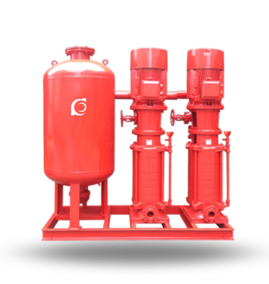
Q(H)YX(DL) Fire Pressure Boosting Equipment is a vertical multistage fire pump system designed for high-pressure water delivery and automatic fire water boosting in fixed fire protection systems.
It delivers rapid pressure buildup, stable hydraulic performance, and reliable emergency water supply during firefighting operation.
It is widely used in high-rise buildings, industrial facilities, commercial complexes, municipal infrastructure, and large public buildings.
Model Designation

Applications
Typical Operating Applications
- High-rise building fire hydrant and sprinkler booster systems
- Industrial plant fire ring main pressure boosting
- Commercial complex centralized fire water supply systems
- Municipal fire booster stations and pipeline networks
- Warehouse and logistics center fire suppression systems
- Fire water supply for hospitals, airports, and transportation hubs
Engineering Advantages
Structural Design Logic and Engineering Performance
- Vertical multistage hydraulic structure provides high discharge pressure with a minimal installation footprint.
- Coaxial suction and discharge simplify piping layout and reduce system head losses.
- Precision-balanced rotor assembly minimizes vibration and extends bearing and seal service life.
- Rapid pressure establishment ensures immediate fire water availability under emergency startup conditions.
- Modular construction facilitates maintenance, overhaul, and lifecycle service management.
System Components
Q(H)YX(DL) Fire Pressure Boosting Equipment Mainly Consists Of:
- Vertical multistage fire pump
- Electric motor
- Pump casing and diffuser assembly
- Mechanical seal system
- Shaft and bearing assembly
- Base frame and coupling
- Fire control cabinet and instrumentation
Technical Specifications
Service Conditions
- Suitable medium: Clean water or non-corrosive fire water
- Maximum solid content: ≤0.1% by volume
- Ambient temperature: 0°C to 40°C
- Installation altitude: ≤1000 m
- Indoor installation with adequate ventilation
Operating Conditions
- Flow rate: 5–200 m³/h
- Head: 40–280 m
- Power range: 4–200 kW
- Speed: 2900 rpm
- Liquid temperature: ≤80°C
- Working pressure: ≤2.5 MPa
Detailed parameter tables are provided below.
Performance Parameters
| Applicable Building |
Sprinkler flow rate
(L/s) |
Operating pressure
at sprinkler head (MPa) |
Applicable building height
(m) |
Recommended water supply unit model
Vertical pump set |
||
| Building type |
Design density
(L/min·m²) |
Coverage area
(m²) |
||||
| Production building | 10 | 300 | 60 | 0.1 | ≤12 | QHYX60-0.24-100XBD-DL-3 |
| Production building | 10 | 300 | 60 | 0.1 | ≤24 | QHYX60-0.4-100XBD-DL-3 |
| Production building | 10 | 300 | 60 | 0.1 | ≤36 | QHYX60-0.6-100XBD-DL-3 |
| Production building | 10 | 300 | 60 | 0.1 | ≤50 | QHYX60-0.8-100XBD-DL-3 |
| Production building | 10 | 300 | 60 | 0.1 | ≤72 | QHYX60-1.0-100XBD-DL-3 |
| Production building | 10 | 300 | 60 | 0.1 | ≤100 | QHYX60-1.2-100XBD-DL-3 |
| Storage building | 15 | 300 | 90 | 0.1 | ≤12 | QHYX90-0.24-150XBD-DL-3 |
| Storage building | 15 | 300 | 90 | 0.1 | ≤24 | QHYX90-0.4-150XBD-DL-3 |
| Storage building | 15 | 300 | 90 | 0.1 | ≤36 | QHYX90-0.6-150XBD-DL-3 |
| Storage building | 15 | 300 | 90 | 0.1 | ≤50 | QHYX90-0.8-150XBD-DL-3 |
| Storage building | 15 | 300 | 90 | 0.1 | ≤72 | QHYX90-1.0-150XBD-DL-3 |
| Storage building | 15 | 300 | 90 | 0.1 | ≤100 | QHYX90-1.2-150XBD-DL-3 |
| Ordinary hazard | 6 | 300 | 40 | 0.1 | ≤12 | QHYX40-0.24-100XBD-DL-3 |
| Ordinary hazard | 6 | 300 | 40 | 0.1 | ≤24 | QHYX40-0.4-100XBD-DL-3 |
| Ordinary hazard | 6 | 300 | 40 | 0.1 | ≤36 | QHYX40-0.6-100XBD-DL-3 |
| Ordinary hazard | 6 | 300 | 40 | 0.1 | ≤50 | QHYX40-0.8-100XBD-DL-3 |
| Ordinary hazard | 6 | 300 | 40 | 0.1 | ≤72 | QHYX40-1.0-100XBD-DL-3 |
| Ordinary hazard | 6 | 300 | 40 | 0.1 | ≤100 | QHYX40-1.2-100XBD-DL-3 |
| Light hazard | 3 | 300 | 15 | 0.1 | ≤12 | QHYX15-0.24-65XBD-DL-3 |
| Light hazard | 3 | 300 | 15 | 0.1 | ≤24 | QHYX15-0.4-65XBD-DL-3 |
| Light hazard | 3 | 300 | 15 | 0.1 | ≤36 | QHYX15-0.6-65XBD-DL-3 |
| Light hazard | 3 | 300 | 15 | 0.1 | ≤50 | QHYX15-0.8-65XBD-DL-3 |
| Light hazard | 3 | 300 | 15 | 0.1 | ≤72 | QHYX15-1.0-65XBD-DL-3 |
| Light hazard | 3 | 300 | 15 | 0.1 | ≤100 | QHYX15-1.2-65XBD-DL-3 |
| Users can select appropriate models according to the parameters provided. | ||||||
How to Select a Pump Model
- Determine required fire flow according to hydrant, sprinkler, or combined system demand.
- Calculate total dynamic head including static lift, friction losses, and residual terminal pressure.
- Verify motor power based on rated duty point and starting method requirements.
- Confirm standby pump redundancy and automatic changeover requirements.
- Ensure compliance with applicable fire codes, electrical standards, and emergency power systems.
Engineering Notes
- The equipment shall be installed downstream of the fire water source or fire storage tank.
- Automatic startup shall be initiated by pressure switch, fire alarm signal, or manual command.
- A dedicated circulation test line is recommended for routine inspection and performance verification.
- Standby pump configuration is recommended for all critical fire protection installations.
- Installation and commissioning shall comply with NFPA, EN, GB, or project-specific fire standards.
Compliance & Quality Assurance
- Hydraulic performance testing for each pump unit
- Hydrostatic pressure testing of all pressure-retaining components
- Rotor dynamic balance verification before final assembly
- Electrical control panel function and interlock testing
- Full material traceability for pressure-bearing components
- Optional third-party witness inspection and factory acceptance testing
Safety Notice
- Do not operate the pump under dry-running conditions.
- Ensure suction piping is fully primed before startup.
- Disconnect and lock out electrical power before maintenance.
- Periodically verify automatic startup, standby switching, and alarm functions.
OEM & Customization
This pump series supports engineered configuration and duty-based matching. Technical adjustments can be made according to system requirements and installation conditions.
Available options include:
- Motor voltage and frequency
- Mechanical seal type and flushing arrangement
- Wetted parts material selection
- Fire control cabinet configuration and communication protocol
- Surface coating and corrosion protection
Configuration is determined based on duty point and project specifications.
FAQs
Q: Can the pump operate under VFD control?
A: Yes, VFD control is available for pressure maintenance, system testing, and energy-saving standby operation.
Q: What is the maximum allowable working pressure?
A: The standard maximum working pressure is 2.5 MPa.
Q: What sealing options are available?
A: Standard mechanical seals and cartridge mechanical seals are available.
Q: Is a standby pump required?
A: A standby pump is strongly recommended for critical fire protection systems.
Q: What standards does the equipment comply with?
A: It can be configured to comply with NFPA, EN, GB, and project-specific requirements.
Q: Can the unit integrate with fire alarm and BMS systems?
A: Yes, dry contacts and communication interfaces are available as standard or optional.
Q: What is the allowable liquid temperature?
A: Standard liquid temperature is up to 80°C.