Product Overview
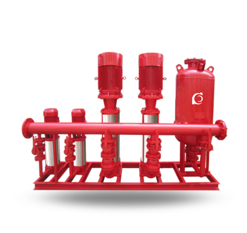
The QHYX-GDL Fire Sprinkler Water Supply System (equipped with an XBD-GDL multistage fire pump) is a tankless fire water supply package integrating the pump set, control system, and pressure boosting & stabilizing devices.
The stabilizing device stores hydraulic energy and maintains network pressure to compensate for minor water draw-off and normal pipeline leakage. When a large demand causes a pressure drop in the network, the pump set starts automatically to ensure continuous water supply.
Model Designation
 Key Features
-
Tankless configuration with fast response.
-
Supports two operating modes: pneumatic pressure water supply and variable-frequency water supply.
-
Supports parallel operation of 1–4 pumps (expandable as required).
-
Coordinated/alternating operation between the main pump and low-flow pressure stabilizing pump improves overall efficiency and reduces energy consumption.
Engineering Summary
Depending on operating requirements, the system can be configured as a pneumatic pressure water supply system or a variable-frequency water supply system, each with different operating characteristics.
It is applicable to domestic water supply, fire-fighting water supply, industrial water supply, sprinkler systems, and related services. The main pump set works in coordination with the auxiliary pressure stabilizing unit (low-flow pump set). Under low-flow conditions, alternating operation is achieved to improve overall efficiency and further reduce energy consumption.
Applications
Applicable to:
-
Fire sprinkler water supply systems
-
Fire-fighting water supply and pressure stabilizing systems
-
Domestic and industrial water supply systems
System Configuration
System Components
Design Basis
System water supply capacity is determined by the pump set, while coordinated operation is managed by the control system. The pressure boosting and stabilizing devices are a key part of automatic control, maintaining network pressure by storing hydraulic energy and compensating for minor demand and normal pipeline leakage.
Selection & Operating Principles
Demand Applications
When a large water demand occurs and causes network pressure to drop, the pump unit starts automatically to ensure continuous water supply.
Intermittent Applications
Under low-flow or zero-flow pressure-maintaining conditions, the system maintains stable network pressure. The boosting/stabilizing device compensates for minor demand and normal pipeline leakage. The main pump avoids frequent starts under low-flow conditions, reducing mechanical wear and extending service life.
Operating Principles
The control system enables automatic start/stop and mode switching. The stabilizing device maintains network pressure and provides pressure compensation. When pressure drops, the pump set is automatically brought online, ensuring stable water supply under long-term continuous operation.
Pumps
Unit Description
The system adopts a centralized pump-set arrangement consisting of a main pump unit and a low-flow pressure stabilizing pump set working in coordination. Automatic control logic coordinates operation and minimizes manual intervention, making it suitable for long-term continuous service.
Pneumatic Pumps (H3)
The system supports the pneumatic pressure water supply mode and can be configured accordingly based on operating requirements. Together with the variable-frequency mode, it allows matching different project operating characteristics and maintenance needs.
Technical Service
Technical Specifications
-
Operating modes: pneumatic pressure water supply / variable-frequency water supply
-
Pump arrangement: parallel operation of 1–4 pumps (expandable as required)
-
Control functions: automatic start/stop, mode switching, coordinated operation
Service Conditions
The system operates under coordinated control with automatic start/stop and operating mode switching, making it suitable for long-term continuous operation. It maintains stable pipeline pressure under low-flow or zero-flow pressure-maintenance conditions, and automatically starts the pump set to ensure continuous water supply when a sudden increase in demand causes network pressure to drop.
Environmental Requirements
No explicit environmental parameters (e.g., ambient temperature, humidity) are provided in the original text; therefore, no additional parameters are added here.
Electrical Control Functions
The control system manages coordinated pump operation, automatic start/stop control, and operating mode switching. It minimizes manual intervention and works with the pressure boosting & stabilizing devices to maintain network pressure and provide pressure compensation.
Operating Instructions
The system maintains stable pressure under low-flow/zero-flow conditions. When sudden demand causes network pressure to drop, the pump set starts automatically to ensure supply continuity and meet high-reliability requirements.
Installation & Dimensions
1. Selection of pumps for variable-frequency constant-pressure water supply equipment
| 1) Selection of water supply height for variable-frequency constant-pressure water supply equipment |
|
Equipment head (m)
|
20
|
26
|
32
|
40
|
50
|
60
|
70
|
80
|
100
|
120
|
|
Water supply height (m)
|
10
|
14
|
18
|
25
|
32
|
38
|
46
|
55
|
72
|
88
|
| 2) Selection of number of service households for variable-frequency constant-pressure water supply equipment |
|
Equipment flow (m³/h)
|
6
|
12
|
18
|
25
|
36
|
50
|
|
Number of households served
|
20–30
|
40–60
|
60–100
|
100–150
|
150–200
|
200–300
|
|
Equipment flow (m³/h)
|
75
|
100
|
150
|
200
|
250
|
|
Number of households served
|
400–500
|
600–1000
|
1000–1500
|
1500–2000
|
2000–3000
|
|
Applicable buildings
|
Spray flow
(L/s)
|
Sprinkler operating
pressure (MPa)
|
Applicable building height
(m)
|
Recommended packaged water supply model
Vertical pump set
|
|
Building type
|
Design spray density
(L/min·m²)
|
Coverage area
(m²)
|
|
Industrial (production) building
|
10
|
300
|
60
|
0.1
|
≤12
|
QHYX60-0.24-100 XBD-GDL-3
|
|
Industrial (production) building
|
10
|
300
|
60
|
0.1
|
≤24
|
QHYX60-0.4-100 XBD-GDL-3
|
|
Industrial (production) building
|
10
|
300
|
60
|
0.1
|
≤36
|
QHYX60-0.6-100 XBD-GDL-3
|
|
Industrial (production) building
|
10
|
300
|
60
|
0.1
|
≤50
|
QHYX60-0.8-100 XBD-GDL-3
|
|
Industrial (production) building
|
10
|
300
|
60
|
0.1
|
≤72
|
QHYX60-1.0-100 XBD-GDL-3
|
|
Industrial (production) building
|
10
|
300
|
60
|
0.1
|
≤100
|
QHYX60-1.2-100 XBD-GDL-3
|
|
Storage building
|
15
|
300
|
90
|
0.1
|
≤12
|
QHYX90-0.24-150 XBD-GDL-3
|
|
Storage building
|
15
|
300
|
90
|
0.1
|
≤24
|
QHYX90-0.4-150 XBD-GDL-3
|
|
Storage building
|
15
|
300
|
90
|
0.1
|
≤36
|
QHYX90-0.6-150 XBD-GDL-3
|
|
Storage building
|
15
|
300
|
90
|
0.1
|
≤50
|
QHYX90-0.8-150 XBD-GDL-3
|
|
Storage building
|
15
|
300
|
90
|
0.1
|
≤72
|
QHYX90-1.0-150 XBD-GDL-3
|
|
Storage building
|
15
|
300
|
90
|
0.1
|
≤100
|
QHYX90-1.2-150 XBD-GDL-3
|
|
Ordinary hazard
|
6
|
300
|
40
|
0.1
|
≤12
|
QHYX40-0.24-100 XBD-GDL-3
|
|
Ordinary hazard
|
6
|
300
|
40
|
0.1
|
≤24
|
QHYX40-0.4-100 XBD-GDL-3
|
|
Ordinary hazard
|
6
|
300
|
40
|
0.1
|
≤36
|
QHYX40-0.6-100 XBD-GDL-3
|
|
Ordinary hazard
|
6
|
300
|
40
|
0.1
|
≤50
|
QHYX40-0.8-100 XBD-GDL-3
|
|
Ordinary hazard
|
6
|
300
|
40
|
0.1
|
≤72
|
QHYX40-1.0-100 XBD-GDL-3
|
|
Ordinary hazard
|
6
|
300
|
40
|
0.1
|
≤100
|
QHYX40-1.2-100 XBD-GDL-3
|
|
Light hazard
|
3
|
300
|
15
|
0.1
|
≤12
|
QHYX15-0.24-65 XBD-GDL-3
|
|
Light hazard
|
3
|
300
|
15
|
0.1
|
≤24
|
QHYX15-0.4-65 XBD-GDL-3
|
|
Light hazard
|
3
|
300
|
15
|
0.1
|
≤36
|
QHYX15-0.6-65 XBD-GDL-3
|
|
Light hazard
|
3
|
300
|
15
|
0.1
|
≤50
|
QHYX15-0.8-65 XBD-GDL-3
|
|
Light hazard
|
3
|
300
|
15
|
0.1
|
≤72
|
QHYX15-1.0-65 XBD-GDL-3
|
|
Light hazard
|
3
|
300
|
15
|
0.1
|
≤100
|
QHYX15-1.2-65 XBD-GDL-3
|
| Users can select suitable models according to the parameters provided above. |
Operating Manual
General Description
-
The boosting and pressure-stabilizing equipment is a fire pressure boosting and stabilizing system developed and designed in accordance with Document [1996] No.108 of the Ministry of Construction of the People’s Republic of China (issued in August 1996), and it also complies with Standard Drawing 98S205 (formerly 98S176).
-
This boosting and stabilizing equipment is designed to solve cases in temporary high-pressure fire water supply systems where the installation height of an elevated fire water tank cannot meet the required static pressure at the most unfavorable point of the system, and therefore additional boosting facilities must be provided. It is fire-dedicated boosting and pressure-stabilizing equipment (hereinafter referred to as “the equipment”).
-
The equipment is applicable to multi-storey and high-rise building projects that require boosting facilities, including fire hydrant water supply systems and wet automatic sprinkler systems. It is also applicable to various fire-fighting and domestic water supply systems.
-
The equipment consists of an SQL diaphragm-type air-pressure water tank (air-pressure tank), an XBD-GDL multistage fire hydrant pump, a control panel (control cabinet), instruments, and piping accessories.
-
The equipment is designed in accordance with the “Code for Fire Protection Design of Tall Buildings” (GB50045-95) and the “Code for Design of Air-Pressure Water Supply System” (CECS76:95), together with related technical parameters.
Design Technical Conditions
-
Relevant design technical conditions for this equipment:
-
Working pressure of SQL air-pressure tank: 0.6 MPa, 1.0 MPa, 1.6 MPa.
-
Fire storage water volume of SQL air-pressure tank: greater than 150 L, 300 L, 450 L.
-
Stabilizing water volume of SQL air-pressure tank: greater than 50 L.
-
Pressure difference of buffer water volume in SQL air-pressure tank: 0.02–0.03 MPa; pressure difference of stabilizing water volume: 0.05–0.06 MPa.
-
Working pressure ratio: a/b value within 0.6–40 ℃.
Operating Principle
-
The equipment must provide the following two functions:
-
Keep the most unfavorable point of the fire water supply pipeline system always at the required fire pressure;
-
Ensure that the air-pressure tank always stores 30 seconds of fire water volume.
By setting the operating pressures P1, P2, Ps1 and Ps2 on the air-pressure tank, the pump operating conditions are controlled to realize pressure boosting and pressure stabilizing. P1 is the required fire pressure at the most unfavorable point (MPa); P2 is the start pressure of the fire pump (MPa); Ps1 is the start pressure of the pressure-stabilizing pump (MPa); Ps2 is the stop pressure of the pressure-stabilizing pump (MPa).
Complete Operating Control Process
-
According to calculation, the required fire pressure P1 at the most unfavorable point of the fire hydrant system or automatic sprinkler system is obtained and adopted as the inflation pressure of the air-pressure tank.
Based on this, together with the selected specifications and a/b value of the air-pressure tank, P2 is calculated, and:
Ps1 = P2 + (0.02–0.03)
Ps2 = Ps1 + (0.05–0.06)
During normal operation, if leakage causes a pressure drop in the pipeline system, the pressure-stabilizing pump will continuously replenish water and maintain pressure, repeatedly operating between Ps1 and Ps2 (start/stop). Once a fire occurs and system water demand increases sharply, pressure drops from Ps1 (Ps1 → Ps2). When it falls to P2, an alarm signal is generated and the fire pump starts immediately (manual or automatic start as determined by the designer). After the fire pump starts, the stabilizing pump stops automatically. The equipment control function can be restored manually only after the fire pump stops.
Equipment Classification
-
Equipment classification:
-
According to installation location: upper-mounted type (I) and lower-mounted type (II);
-
According to tank arrangement: vertical (L) and horizontal (W);
-
According to type of fire water supply system served: fire hydrant water supply system (X), automatic sprinkler system (Z), and combined fire hydrant & sprinkler system (XZ).
Model Designation
-
Equipment model designation:
Examples: ① ZW(L)—I—X—10—0.16
② ZW(W)—II—X—C
Definition of P1
-
Calculation of P1:
P1 is the fire pressure required at the most unfavorable fire hydrant or sprinkler head of the fire water supply system. It is the minimum working pressure of the equipment and the basic parameter for selecting this equipment.
Calculation Method of P1
-
When the equipment is installed at the bottom level and draws water from a tank, P1 of the fire hydrant system is calculated as:
P1 = H1 + H2 + H3 + H4 (mH2O)
H1 – geometric height from the low water level of the tank to the most unfavorable fire hydrant (mH2O);
H2 – sum of friction and local pressure losses of the pipeline system (mH2O);
H3 – pressure loss in hose and hydrant itself (mH2O);
H4 – pressure required to achieve the effective jet length of the nozzle (mH2O).
-
When the equipment is installed in the high-level tank room and supplied by gravity from the tank, and the most unfavorable fire hydrant is lower than the equipment, P1 of the fire hydrant system is calculated as:
P1 = H3 + H4 (mH2O)
-
When the equipment is installed at the bottom level and draws water from a tank, P1 of the automatic sprinkler system is calculated as:
P1 = ∑H + Ho + Hr + Z (mH2O)
∑H – sum of friction and local pressure losses from sprinkler pipes to the most unfavorable sprinkler head (mH2O);
Ho – operating pressure of the most unfavorable sprinkler head (mH2O);
Hr – local head loss of the alarm valve (mH2O);
Z – geometric height between the most unfavorable sprinkler head and the low water level of the tank (or supply main) (mH2O).
-
When the equipment is installed in the high-level tank room and supplied by gravity from the tank, and the most unfavorable sprinkler head is lower than the equipment, P1 of the automatic sprinkler system is also calculated as:
P1 = ∑H + Ho + Hr + Z (mH2O)
-
When the air-pressure tank and the pump are installed at different locations, P1 shall be recalculated separately.
Additional Notes
-
Additional notes:
-
Pressure boosting criterion: P1 is the minimum working pressure of the equipment and must meet the required fire pressure at the most unfavorable point of the fire water supply system. For fire hydrant systems, it must meet the requirement of effective jet length of the most unfavorable hydrant nozzle, and it shall not be determined only by a static pressure of 0.07 MPa or 0.15 MPa.
-
When calculating P1, the flow used for friction and local losses of the pipeline system should be the fire water flow in the early stage of fire, such as two fire hydrant streams of 2×5 L/s = 10 L/s or 2×2.5 L/s = 5 L/s for hydrant systems, and 5 sprinkler heads of 5×1 L/s = 5 L/s for automatic sprinkler systems.
-
Main components: the air-pressure tank must provide the required fire storage water volume, stabilizing water volume and buffer water volume of the fire water supply system. Its diameter and size are determined by the a/b value. For fire hydrant systems, storage volume of the air-pressure tank shall not be less than 300 L; for automatic sprinkler systems, not less than 150 L; for combined fire hydrant & sprinkler systems, not less than 450 L.
-
Two pressure-stabilizing pumps (one duty, one standby) are provided. The stabilizing pump flow shall be able to replenish the actual stabilizing water volume in the air-pressure tank within 3 minutes. The stabilizing pump head should be selected in the high-efficiency area of the pump curve at (Ps1 + Ps2)/2. The function of the equipment is to ensure a 30-second fire water storage with sufficient pressure in the early stage of a fire, before the main fire pump starts and reaches full load.
-
Fire hydrant systems and automatic sprinkler systems may share one set of booster & stabilizing equipment. When a fire occurs and tank pressure drops to P2, the system sends signals to the fire control center or fire pump room. After confirmation, the fire hydrant pump or sprinkler pump shall be started accordingly.
-
In fire hydrant systems, upper-mounted equipment is preferred to lower-mounted. The upper-mounted type requires lower pump head because P1 only needs to overcome hose and nozzle losses and provide effective jet length. The air-pressure tank inflation pressure is lower, with lower design pressure, saving steel consumption and operating costs.
-
Electrical control performance:
-
The control system has both automatic and manual functions and can be networked with the fire control center or fire pump room.
-
Two pressure-stabilizing pumps are configured as duty/standby and operate alternately with automatic changeover.
-
Under normal conditions, the fire main is kept at high pressure and the tank stores a certain volume of water. When system pressure drops to Ps1 due to leakage, Pump No.1 starts automatically and stops when pressure rises to Ps2. Next time, when pressure drops to Ps1 again, Pump No.2 starts automatically. They alternately operate so that system pressure is always maintained between Ps1 and Ps2.
-
Once a fire occurs and system pressure drops from Ps1 to Ps2, a start signal and audible/visual alarm for the main fire pump are generated. After the main fire pump starts and returns a feedback signal, the control power of the stabilizing pumps is cut off. Manual reset is required afterwards to restore the control function.
-
The control system provides a maintenance mode. If Pump No.1 fails during operation, Pump No.2 can be easily switched on. If Pump No.2 fails, Pump No.1 can be enabled so that the equipment can still operate normally while one pump is under maintenance.
-
For the size of the control cabinet, control principles and main components, refer to the company’s electrical automatic control manual.
Manufacturing, Materials & Installation Requirements
-
Diaphragm air-pressure water tanks are manufactured according to national standard drawing set 91SS852.
-
Piping uses seamless steel pipe, hot-dip galvanized steel pipe, or hot-dip galvanized seamless steel pipe.
-
The equipment is supported by an integrated steel base. The support form of the diaphragm air-pressure tank in this drawing set is skirt support, but saddle-type support can also be used.
-
For upper-mounted equipment, vibration isolation measures shall be provided. When installing rubber vibration isolators under the pump unit, measures must be taken to prevent the pump unit from tipping over. After installing the vibration isolators, when installing inlet and outlet pipes, fittings and accessories, measures must be taken to prevent the pump unit from tilting to ensure safe construction.
-
The air-pressure tank is equipped with a drain device. Safety valves, remote pressure gauges and other accessories shall be installed on the pipeline system.
-
Drainage facilities shall be provided around the equipment for draining water during maintenance or in case of accidental leakage.
-
Sufficient clearance shall be provided between the equipment and walls or other equipment, generally not less than 700 mm.
-
The equipment shall undergo overall hydrostatic strength test and tightness test in accordance with current relevant standards.
-
The outer surface of connecting pipes, fittings and air-pressure tank shall be coated with two coats of anti-rust paint. The internal surface of the air-pressure tank shall be coated with non-toxic anticorrosive paint.
-
Installation of pumps, motors and pipelines shall comply with relevant technical specifications.
Operation Notes
-
Operation notes:
-
Before commissioning, initial commissioning shall be performed by the manufacturer. After commissioning, the air inlet of the pressure tank shall not be removed at will to avoid air leakage.
-
During operation, no full-time operator is required, but regular inspection is necessary.
Pump Series & Electrical Control Reference
-
The pumps configured in this equipment are based on the company’s XBD_DL vertical multistage fire pump / XBD-LG vertical multistage fire pump / XBD-ISG vertical single-stage fire pump series. When other pumps are adopted, they shall be selected according to the flow and head requirements listed in the tables.
-
The electrical control part of this equipment can be designed with reference to the company’s electrical automatic control manual.
OEM & Custom
Chaodun Pump offers complete OEM and ODM customization for firefighting sprinkler water systems. We provide options for pump configurations, control cabinet design, and pressure settings to suit various regional standards. All equipment undergoes strict testing to ensure reliability and durability under emergency operation.
FAQs
- Q1: What is the QHYX-GDL Fire Sprinkler Water Supply Equipment used for?
It is used for automatic water supply and pressure control in firefighting sprinkler and building safety systems.
- Q2: Can I customize the pressure or pump specifications?
Yes, Chaodun Pump provides OEM/ODM customization for flow rate, pressure, and control configurations.
- Q3: What components are included in the system?
The equipment includes multistage pump units, control panels, and a pressure stabilization tank for reliable operation.
- Q4: What is the benefit of variable frequency control?
It maintains precise constant pressure, reduces energy consumption, and ensures smooth startup with low noise.
- Q5: What’s the difference between air pressure and variable frequency types?
Air pressure systems are simpler and more cost-effective, while variable frequency types offer higher precision and energy savings.
- Q6: Is it suitable for non-fire applications?
Yes, it can also be used for residential, industrial, and irrigation water supply systems.
- Q7: Do you provide export certificates or performance test data?
Yes, we supply all necessary documentation, certificates, and testing reports for international projects.