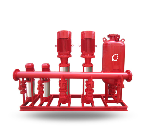
QHYX-GDL Fire Sprinkler Water Supply Equipment

QHYX-GDL Fire Sprinkler Water Supply Equipment

Model Code Explanation Product Description QHYX-GDL fire sprinkler water supply equipment (equipped with XBD-GDL ver...

Product Description

Model Code Explanation

QHYX GDL Fire Sprinkler Water Supply Equipment typy1

Product Description

QHYX-GDL fire sprinkler water supply equipment (equipped with XBD-GDL vertical multistage fire pump) is a new type of tankless water supply unit, consisting of three major parts: pump unit, control system, and booster & pressure-stabilizing unit. The water supply capacity is determined by the pump unit, the coordinated operation of the system is controlled by the control system, and the main function of the booster & pressure-stabilizing unit is to store energy and maintain pressure, to handle small water consumption and normal pipeline leakage. It is also an essential part of the automatic control system. When there is a large water demand, the pressure in the pipe network drops and the pump starts automatically to supply water.
QHYX-GDL fire sprinkler water supply equipment (equipped with XBD-GDL multistage fire hydrant pump) can be divided into air-pressure water supply units and variable-frequency water supply units according to different operating modes, each with its own characteristics. It is widely used in domestic water supply, fire protection, industrial water supply and sprinkler systems across various applications.
The pump is the core of the water supply unit and is the fundamental guarantee for the water supply performance of the system. The pump matched with the water supply unit is universal and can be any pump with suitable flow and head parameters. Depending on the required flow and head, 1–4 or more pumps can be operated in parallel. The pump unit, together with another booster and pressure-stabilizing power supply unit (small-flow pump group), can alternate operation with the main pump in the low-flow range to improve efficiency and further reduce energy consumption.
According to different operating modes, the equipment can be divided into domestic type, fire-fighting type, sprinkler type, and combined domestic & fire type, etc.

Selection Basis

The basic basis for selecting an automatic water supply unit is the design water supply flow and the required water supply pressure (pump head). In addition, the type of flow variation according to the application must also be considered.
Continuous type: situations where the flow rate rarely drops to zero within a day, or where normal leakage in the pipeline itself maintains a certain flow, such as booster systems for large hotels, restaurants and industrial & mining enterprises.
Intermittent type: where there is a long low-demand period with very small flow or almost zero flow, such as small office buildings, office towers, commercial-residential buildings, various residential buildings, and certain process water systems.
At the same time, changes in flow within specific time periods, seasonal variations in water consumption, and differences in water usage between different regions and applications should also be fully considered.
For fire sprinkler water supply systems, air-pressure type water supply units are generally recommended. As the system remains in a long-term pressure-maintaining state with no actual flow variation, the air-pressure water supply unit can compensate for normal pipeline leakage. By adding a small-flow auxiliary pump, the main pump does not need to start under normal conditions, thereby saving energy.
Advantages of variable-frequency water supply units: they can provide constant-pressure water supply, and the constant-pressure value can be adjusted within a certain range. The constant-pressure accuracy is generally less than 0.02 MPa. Variable-frequency speed control is a highly efficient, energy-saving method, and compared with conventional air-pressure water supply units, it can save on average about 20% energy. In addition, the inrush current at variable-frequency starting is small, mechanical impact on the pump is small, and noise at low-speed operation is low.
Advantages of air-pressure water supply units: relatively low investment cost, simple control technology, convenient service and easy maintenance.

Selection Guide

I. Pump Selection for Variable-Frequency Constant-Pressure Water Supply Units

1. Selection of water supply height for the water supply unit
Unit head (m)
20
26
32
40
50
60
70
80
100
120
Water supply height (m)
10
14
18
25
32
38
46
55
72
88


2. Selection of number of users served by the water supply unit
Unit flow rate (m³/h)
6
12
18
25
36
50
Number of households served
20–30
40–60
60–100
100–150
150–200
200–300


Unit flow rate (m³/h)
75
100
150
200
250
Number of households served
400–500
600–1000
1000–1500
1500–2000
2000–3000


Performance Parameters

Applicable Building
Sprinkler flow rate
(L/s)
Operating pressure
at sprinkler head
(MPa)
Applicable building height
(m)
Recommended water supply unit model
Vertical pump set
Building type
Design density
(L/min·m²)
Coverage area
(m²)
Production building
10
300
60
0.1
≤12
QHYX60-0.24-100XBD-GDL-3
Production building
10
300
60
0.1
≤24
QHYX60-0.4-100XBD-GDL-3
Production building
10
300
60
0.1
≤36
QHYX60-0.6-100XBD-GDL-3
Production building
10
300
60
0.1
≤50
QHYX60-0.8-100XBD-GDL-3
Production building
10
300
60
0.1
≤72
QHYX60-1.0-100XBD-GDL-3
Production building
10
300
60
0.1
≤100
QHYX60-1.2-100XBD-GDL-3
Storage building
15
300
90
0.1
≤12
QHYX90-0.24-150XBD-GDL-3
Storage building
15
300
90
0.1
≤24
QHYX90-0.4-150XBD-GDL-3
Storage building
15
300
90
0.1
≤36
QHYX90-0.6-150XBD-GDL-3
Storage building
15
300
90
0.1
≤50
QHYX90-0.8-150XBD-GDL-3
Storage building
15
300
90
0.1
≤72
QHYX90-1.0-150XBD-GDL-3
Storage building
15
300
90
0.1
≤100
QHYX90-1.2-150XBD-GDL-3
Ordinary hazard
6
300
40
0.1
≤12
QHYX40-0.24-100XBD-GDL-3
Ordinary hazard
6
300
40
0.1
≤24
QHYX40-0.4-100XBD-GDL-3
Ordinary hazard
6
300
40
0.1
≤36
QHYX40-0.6-100XBD-GDL-3
Ordinary hazard
6
300
40
0.1
≤50
QHYX40-0.8-100XBD-GDL-3
Ordinary hazard
6
300
40
0.1
≤72
QHYX40-1.0-100XBD-GDL-3
Ordinary hazard
6
300
40
0.1
≤100
QHYX40-1.2-100XBD-GDL-3
Light hazard
3
300
15
0.1
≤12
QHYX15-0.24-65XBD-GDL-3
Light hazard
3
300
15
0.1
≤24
QHYX15-0.4-65XBD-GDL-3
Light hazard
3
300
15
0.1
≤36
QHYX15-0.6-65XBD-GDL-3
Light hazard
3
300
15
0.1
≤50
QHYX15-0.8-65XBD-GDL-3
Light hazard
3
300
15
0.1
≤72
QHYX15-1.0-65XBD-GDL-3
Light hazard
3
300
15
0.1
≤100
QHYX15-1.2-65XBD-GDL-3
Users can select appropriate models according to the parameters provided.


General Description

I. The booster and pressure-stabilizing unit is a new type of fire booster and pressure-stabilizing equipment developed and designed in accordance with Document [1996] No.108 issued by the Ministry of Construction of the People’s Republic of China in August 1996, and also complies with the provisions of 98S205 (formerly 98S176).

II. This booster and pressure-stabilizing unit is designed to solve the case where the high-level fire-fighting water tank provided for the temporary high-pressure fire water supply system cannot meet the required static pressure at the most unfavorable point in the system, and therefore a booster facility must be installed. A dedicated booster and pressure-stabilizing unit for fire service (hereinafter referred to as the “unit”) has been designed.

III. This unit is suitable for fire hydrant water supply systems and wet automatic sprinkler systems that require booster facilities in multi-storey and high-rise buildings, as well as various fire water supply and domestic water supply systems.

IV. The “unit” consists of an SQL diaphragm pressure tank, XBD-GDL multistage fire hydrant pump, electrical control cabinet, instruments, pipework and accessories.

V. The design of this unit follows the relevant technical parameters specified in the national standard “Code for Fire Protection Design of High-Rise Civil Buildings” (hereinafter referred to as “High-Rise Code”) GB50045-95 and the “Code for Design of Air-Pressure Water Supply” CECS76:95.

VI. Design technical conditions of this “unit”:

1. Working pressure of SQL pressure tank: 0.6 MPa, 1.0 MPa, 1.6 MPa.

2. Fire water storage volume of SQL pressure tank: greater than 150 L, 300 L, 450 L.

3. Pressure-stabilizing water volume of SQL pressure tank: greater than 50 L.

4. Pressure difference of buffer water volume in SQL pressure tank: 0.02–0.03 MPa; pressure difference of pressure-stabilizing water volume: 0.05–0.06 MPa.

5. Working pressure ratio: a/b value is 0.6–4.0.

VII. Operating Principle of the “Unit”

This “unit” must satisfy the following two functions:

1. Ensure that the most unfavorable point in the fire water supply pipe network always maintains the required fire-fighting pressure.

2. Ensure that the pressure tank always stores 30 seconds of fire water volume. By using the operating pressures P1, P2, Ps1 and Ps2 set for the pressure tank, the operating conditions of the pump are controlled to achieve the functions of boosting and pressure stabilization. P1 is the required fire pressure (MPa) at the most unfavorable point; P2 is the start pressure (MPa) of the fire pump; Ps1 is the start pressure (MPa) of the jockey pump; Ps2 is the stop pressure (MPa) of the jockey pump.

VIII. Full Operating Control Process

According to calculations, the required fire pressure P1 at the most unfavorable point of the fire hydrant system or automatic sprinkler system is obtained and used as the filling pressure of the pressure tank. Based on this and the selected specifications and a/b value of the pressurized water tank, P2 is determined, and then the following are set:

Ps1 = P2 + (0.02–0.03)
Ps2 = Ps1 + (0.05–0.06)

Under normal conditions, when there is pipeline leakage or pressure drop in the system, the jockey pump continuously replenishes water to maintain pressure, and operates repeatedly between Ps1 (start) and Ps2 (stop). Once a fire occurs and the system loses a large amount of water, causing the pressure to fall from Ps1 (Ps1 → Ps2) down to P2, an alarm signal is issued and the fire pump is started immediately (manual or automatic start is determined by the designer). After the fire pump starts, the jockey pump stops automatically and remains off until the fire pump stops. Then the control function of the “unit” is restored manually.

IX. Classification of the “Unit”

According to installation position:

– Top-mounted type (denoted by I)

– Bottom-mounted type (denoted by II)

According to tank arrangement:

– Vertical type (denoted by L)

– Horizontal type (denoted by W)

According to the fire water supply system served by the unit:

– Fire hydrant water supply system (denoted by X)

– Automatic sprinkler system (denoted by Z)

– Combined fire hydrant and automatic sprinkler water supply system (denoted by XZ)

X. Model Designation of the “Unit”

Example: ① ZW(L)—I—X—10—0.16
ZW(W)—II—X—C

XI. Calculation of P1

P1 refers to the required fire pressure at the most unfavorable fire hydrant or sprinkler head in the fire water supply system. It is the minimum operating pressure of this “unit” and is the fundamental parameter that must be mastered when selecting this equipment.

1. When this “unit” is installed at the lowest floor and draws water from a water tank, the calculation formula for the fire hydrant system is:

P1 = H1 + H2 + H3 + H4 (mH2O);

H1 — Geometric height (mH2O) from the minimum water level in the tank to the most unfavorable fire hydrant;

H2 — Sum of frictional and local pressure losses (mH2O) in the pipeline system;

H3 — Pressure loss (mH2O) of hose and fire hydrant assembly;

H4 — Pressure (mH2O) required for the water jet to achieve the specified effective range.

2. When the “unit” is installed in a high-level water tank room and draws water by gravity from the tank, and the most unfavorable fire hydrant is located below the “unit”, the calculation formula for the fire hydrant system is:

P1 = H3 + H4 (mH2O)

3. When the “unit” is installed at the lowest floor and draws water from a water tank, the calculation formula for an automatic sprinkler system is:

P1 = ∑H + Ho + Hr + Z (mH2O)

∑H — Sum of frictional and local pressure losses (mH2O) from the water supply source to the most unfavorable sprinkler head;

Ho — Operating pressure (mH2O) at the most unfavorable sprinkler head;

Hr — Local head loss (mH2O) at the alarm valve;

Z — Geometric height (mH2O) between the most unfavorable sprinkler head and the minimum water level in the tank (or supply main).

4. When the “unit” is installed in a high-level tank room and draws water by gravity from the tank, and the most unfavorable sprinkler head is located below the unit, the calculation formula for the automatic sprinkler system is:

P1 = ∑H + Ho + Hr + Z (mH2O)

5. When the pressure tank and the pump are installed in different locations, P1 should be recalculated accordingly.

XII. Additional Notes

1. Booster standard of this “unit”: P1 is the minimum operating pressure of this “unit” and must meet the fire pressure required at the most unfavorable point of the fire water supply system. For a fire hydrant system, the effective jet range of the most unfavorable fire hydrant must be satisfied. It is not sufficient to take only 0.07 MPa or 0.15 MPa of static pressure as the booster standard.

2. When calculating P1, the flow used to calculate friction and local losses in the pipeline system shall be the fire water demand at the initial stage of fire. For fire hydrant systems, this is generally two hose streams with flow 2×5 (L/s) = 10 (L/s) or 2×2.5 (L/s) = 5 (L/s). For automatic sprinkler systems, it is generally taken as the flow of 5 sprinklers, usually 5×1 (L/s) = 5 (L/s).

3. The main components of this “unit”: the pressurized water tank shall provide the required fire water storage volume, pressure-stabilizing water volume and buffer water volume for the fire water supply system. Based on the determined a/b value, the diameter and specification are calculated. For fire hydrant water supply systems, the storage volume of the pressure tank shall not be less than 300 L; for automatic sprinkler systems, not less than 150 L; for combined fire hydrant and automatic sprinkler systems, not less than 450 L.

4. This “unit” is equipped with two jockey pumps (one duty, one standby). Within 3 minutes, the jockey pump flow should be able to replenish the actual pressure-stabilizing water volume in the pressure tank. The head of the jockey pump should be selected at the high-efficiency section of the pump curve corresponding to (Ps1 + Ps2)/2. The function of this “unit” is to ensure, at the initial stage of a fire before the main fire pump starts, that there is sufficient 30-second fire water volume at the required pressure for initial fire suppression until the main fire pump reaches full load.

5. The fire hydrant water supply system and the automatic sprinkler system can share one booster and pressure-stabilizing unit. When a fire occurs and the pressure in the pressure tank drops to P2, signals are sent to the fire control center or fire pump room from the fire hydrant system or automatic sprinkler system respectively. After confirmation, the corresponding fire hydrant pump or sprinkler pump is started.

6. For fire hydrant water supply systems, the top-mounted type of this “unit” is preferable to the bottom-mounted type. For the top-mounted type, the required pump head is lower, since P1 mainly comprises the pressure losses of the hose and nozzle, and the pressure required to achieve the effective jet range. The charging pressure of the pressure tank is therefore lower, the tank operates at a lower pressure, and both steel consumption and operating cost are reduced.

XIII. Electrical Control Features

1. The electrical control system of this “unit” provides both automatic and manual control functions and can be networked with the fire control center or fire pump room.

2. Two jockey pumps are configured (one duty, one standby) and operate alternately with automatic switching.

3. Normally, the fire pipeline network is maintained at high pressure with a certain storage volume in the tank. When the system pressure drops to Ps1 due to leakage and other reasons, Pump No.1 starts automatically and stops when the pressure rises to Ps2. At the next pressure drop to Ps1, Pump No.2 starts automatically, and so on alternately, ensuring that the system pressure always remains between Ps1 and Ps2.

4. Once a fire occurs and system pressure falls from Ps1 to Ps2, the control system outputs a start signal for the main fire pump together with audible and visual alarms. After the main fire pump starts and returns a feedback signal, the control power of the jockey pumps is cut off. Thereafter the control function is restored manually.

5. The electrical control system provides a maintenance mode. If Pump No.1 fails during operation, the system can be easily switched to Pump No.2. If Pump No.2 fails, it can be switched back to Pump No.1, ensuring that the “unit” can continue normal operation with one pump under maintenance.

6. Specifications and dimensions of the control cabinet, the electrical control principle and the major components are detailed in the company’s dedicated electrical automatic control manual.

XIV. The diaphragm pressure tank is manufactured in accordance with the national standard drawing set 91SS852.

XV. Piping is made of seamless steel pipes, hot-dip galvanized steel pipes, or hot-dip galvanized seamless steel pipes.

XVI. The “unit” adopts an integrated modular steel base as structural support. The support form of the diaphragm pressure tank in this drawing set is designed as a skirt base, but a saddle-type support can also be used.

XVII. When this “unit” is installed in the top-mounted configuration, vibration isolation measures shall be provided. During the installation of rubber vibration isolation pads under the pump unit, measures must be taken to prevent the pump unit from tipping. After the isolation pads are installed, when installing pump suction and discharge pipework, fittings and accessories, measures must also be taken to prevent the pump unit from tilting, so as to ensure safe installation.

XVIII. The pressure tank is equipped with a drain device, and the pipeline system is equipped with a safety valve, remote pressure gauge and other accessories.

XIX. The area surrounding the “unit” shall be provided with drainage facilities to facilitate draining during maintenance or in case of accidental leakage.

XX. There shall be sufficient clearance between the “unit” and walls or other equipment, generally not less than 700 mm.

XXI. The “unit” shall undergo overall hydrostatic testing, strength testing and tightness testing in accordance with the current relevant regulations.

XXII. External surfaces of connecting piping, fittings and the pressure tank shall be coated with two layers of anti-rust paint, and the internal surface of the pressure tank shall be coated with a non-toxic corrosion-resistant coating.

XXIII. Installation of pumps, motors and pipelines shall comply with the relevant technical specifications.

XXIV. Operating Precautions

1. Before the unit is put into operation, commissioning shall be carried out first (by the manufacturer). After commissioning is completed, the charging nozzle of the pressure tank shall not be disassembled at will to prevent air leakage.

2. During operation, the unit does not require dedicated operators on duty, but regular inspections shall be carried out.

XXV. The pumps used in this unit are based on the company’s XBD_DL vertical multistage fire pump / XBD-LG vertical multistage fire pump / XBD-ISG vertical single-stage fire pump series. If other pumps are adopted, appropriate pumps can be selected according to the flow and head requirements listed in the tables.

XXVI. The electrical control part of this unit can be designed with reference to the company’s electrical automatic control manual.

OEM & Custom Solutions

Chaodun Pump provides OEM/ODM customization for QHYX-GDL Fire Sprinkler Water Supply Equipment, including pump type, control cabinet configuration, and pressure settings. All products meet ISO9001, GB50045-95, and CECS76:95 standards, ensuring quality and safety for global export.

FAQs for Oversea Buyers

Q1: What is the QHYX-GDL Fire Sprinkler Water Supply Equipment used for?
It supplies stable fire water pressure for sprinkler and hydrant systems in buildings and factories.

Q2: What control modes are available?
Automatic and manual modes with real-time monitoring and alarm linkage.

Q3: What are the advantages of the variable frequency type?
Precise constant pressure, energy efficiency, and smooth low-noise operation.

Q4: Can the equipment be customized?
Yes, pump configuration, pressure, and control systems can be tailored for different projects.

Q5: What standards does it comply with?
It meets GB50045-95, CECS76:95, and ISO9001 quality standards.

Q6: What is included in the system?
Fire pump, control cabinet, air tank, valves, and connecting pipelines.

Q7: Does Yitie Pump provide international documentation?
Yes, all export models include CE/ISO certificates, test reports, and user manuals.