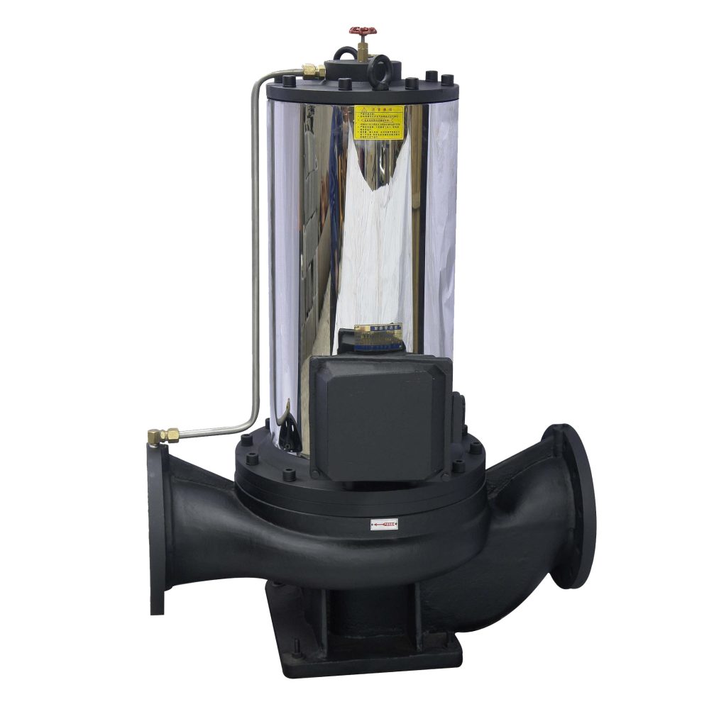
Product Overview
The SPG Vertical In-Line Canned Motor Clean Water Pump uses advanced canned motor design and manufacturing technology. By applying canned motor technology to liquid handling, this series aims to meet both domestic and international market needs. The SPG series performance parameters generally comply with ISO 2858 and JB/T 6878.2-93 standards. The pumps feature standardized designs, high interchangeability, reasonable structure, stable performance, low operational noise, and minimal vibration, making them an ideal replacement for traditional horizontal centrifugal pumps and vertical in-line pumps.
The complete series covers 67 models and 184 specifications, with the following performance range:
Flow: 6.3–108 m3/h
Head: 12.5–125 meters
Motor power: 0.37–160 kW
Speed: 1450 / 2900 RPM
Model Designation

Installation & Dimensions
Outline Drawing

Performance Data
| Name | Material | No. | Name |
| 1 | Pump Casing | 10 | Stator Shield Sleeve |
| 2 | Wear Ring | 11 | Upper Bearing Seat |
| 3 | Impeller | 12 | Rotor End Cover |
| 4 | Lower Bearing Seat | 13 | Stator Shield Sleeve |
| 5 | Motor Terminal Box | 14 | Bearing |
| 6 | Motor Housing | 15 | Pump Cover |
| 7 | Bearing | 16 | Cooling Water Assembly |
| 8 | Stator Assembly | 17 | Shaft |
| 9 | Rotor Assembly |
Performance Curves

Performance Parameters
| Model | Inlet/Outlet Diameter | Flow Rate | Head | Efficiency | Speed | Motor Power | NPSHr | Weight | |
| mm | m3/h | L/S | m | % | r/min | KW | (NPSH)r | Kg | |
| 20-110 | 20 |
1.8
2.5 3.3 |
0.5
0.69 0.91 |
16
15 13.5 |
25
34 35 |
2800 | 0.37 | 2.3 | 25 |
| 20-160 | 20 |
1.8
2.5 3.3 |
0.5
0.69 0.91 |
33
32 30 |
19
25 23 |
2900 | 0.75 | 2.3 | 29 |
| 25-110 | 25 |
2.8
4 5.2 |
0.78
1.11 1.44 |
16
15 13.5 |
34
42 41 |
2900 | 0.55 | 2.3 | 26 |
| 25-125 | 25 |
2.8
4 5.2 |
0.78
1.11 1.44 |
20.6
20 18 |
28
36 35 |
2900 | 0.75 | 2.3 | 28 |
| 25-125A | 25 |
2.5
3.6 4.6 |
0.69
1.0 1.28 |
17
16 14.4 |
35 | 2900 | 0.55 | 2.3 | 27 |
| 25-160 | 25 |
2.8
4 5.2 |
0.78
1.11 1.44 |
33
32 30 |
24
32 33 |
2900 | 1.5 | 2.3 | 39 |
| 25-160A | 25 |
2.6
3.7 4.9 |
0.12
1.03 1.36 |
29
28 26 |
31 | 2900 | 1.1 | 2.3 | 34 |
| 32-100 | 32 |
3.5
5 6.5 |
0.97
0.39 1.8 |
13.2
12.5 11.3 |
40
44 42 |
2900 | 0.75 | 2.3 | 28 |
| 32-125 | 32 |
3.5
5 6.5 |
0.97
0.39 1.8 |
22
20 18 |
40
44 42 |
2900 | 0.75 | 2.3 | 28 |
| 32-125A | 32 |
3.1
4.5 5.8 |
0.86
1.25 1.61 |
17.6
16 14.4 |
43 | 2900 | 0.75 | 2.3 | 28 |
| 32-160 | 32 |
3.5
5 6.5 |
0.97
0.39 1.8 |
33.2
32 30.2 |
48
54 53 |
2900 | 1.5 | 2.0 | 39 |
| 32-160A | 32 |
3.1
4.5 5.8 |
0.86
1.25 1.61 |
29
28 26.3 |
48
54 53 |
2900 | 1.1 | 2.0 | 39 |
| 32-200 | 32 |
3.5
5 6.5 |
0.97
0.39 1.8 |
50.5
50 48 |
34
40 42 |
2900 | 3 | 2.0 | 77 |
| 32-200A | 32 |
2.8
4 5.2 |
0.78
1.11 1.44 |
44.6
44 42.7 |
34
40 42 |
2900 | 2.2 | 2.0 | 74 |
| 32-100(I) | 32 |
4.4
6.3 8.3 |
1.22
1.75 2.32 |
13.2
12.5 11.3 |
48
54 53 |
2900 | 0.75 | 2.0 | 32 |
| 32-100(I)A | 32 |
4.4
6.3 8.3 |
1.22
1.75 2.32 |
13.2
12.5 11.3 |
48
54 53 |
2900 | 0.75 | 2.0 | 32 |
| 32-125(I) | 32 |
4.4
6.3 8.3 |
1.22
1.75 2.32 |
22
20 18 |
48
54 53 |
2900 | 1.1 | 2.3 | 34 |
| 32-125(I)A | 32 |
4.4
6.3 8.3 |
1.22
1.75 2.32 |
17.6
16 14.4 |
40
45 41 |
2900 | 0.75 | 2.3 | 33 |
| 32-160(I) | 32 |
4.4
6.3 8.3 |
1.22
1.75 2.32 |
33.2
32 30.2 |
34
40 42 |
2900 | 2.2 | 2.0 | 47 |
| 32-160(I)A | 32 |
4.1
5.9 7.8 |
1.14
1.64 2.17 |
29
28 26.3 |
34
39 39 |
2900 | 1.5 | 2.3 | 43 |
| 32-160(I)B | 32 |
3.8
5.5 7.2 |
1.06
1.53 2.0 |
25.5
24 22.5 |
34
38 37 |
2900 | 1.1 | 2.3 | 38 |
| 32-200(I) | 32 |
4.4
6.3 8.3 |
1.22
1.75 2.32 |
50.5
50 48 |
26
33 35 |
2900 | 4 | 2.0 | 43 |
| 32-200(I)A | 32 |
4.1
5.9 7.8 |
1.14
1.64 2.17 |
45
44 42 |
26
31 30 |
2900 | 3 | 2.3 | 62 |
| Model | Inlet/Outlet Diameter | Flow Rate | Head | Efficiency | Speed | Motor Power | NPSHr | Weight | |
| mm | m3/h | L/S | m | % | r/min | KW | (NPSH)r | Kg | |
| 40-100 | 40 |
4.4
6.3 8.3 |
1.22
1.75 2.31 |
13.2
12.5 11.3 |
48
54 53 |
2900 | 0.55 | 2.3 | 32 |
| 40-100A | 40 |
3.9
5.6 7.4 |
1.08
1.56 2.06 |
10.6
10 9 |
52 | 2900 | 0.37 | 2.3 | 32 |
| 40-125 | 40 |
4.4
6.3 8.3 |
1.22
1.75 2.31 |
21
20 18 |
41
46 43 |
2900 | 1.1 | 2.3 | 34 |
| 40-125A | 40 |
3.9
5.6 7.4 |
1.08
1.56 2.06 |
17.6
16 14.4 |
40
45 41 |
2900 | 0.75 | 2.3 | 33 |
| 40-160 | 40 |
4.4
6.3 8.3 |
1.22
1.75 2.31 |
33
32 30 |
35
40 40 |
2900 | 2.2 | 2.3 | 47 |
| 40-160A | 40 |
4.1
5.9 7.8 |
1.14
1.64 2.17 |
29
28 26.3 |
34
39 39 |
2900 | 1.5 | 2.3 | 43 |
| 40-160B | 40 |
3.8
5.5 7.2 |
1.06
1.53 2.0 |
25.5
24 22.5 |
34
38 37 |
2900 | 1.1 | 2.3 | 38 |
| 40-200 | 40 |
4.4
6.3 8.3 |
1.22
1.75 2.31 |
51
50 48 |
26
33 32 |
2900 | 4 | 2.3 | 74 |
| 40-200A | 40 |
4.1
5.9 7.8 |
1.14
1.64 2.17 |
45
44 42 |
26
31 30 |
2900 | 3 | 2.3 | 62 |
| 40-200B | 40 |
3.7
5.3 7.0 |
1.03
1.47 1.94 |
38
36 34.5 |
29 | 2900 | 2.2 | 2.3 | 52 |
| 40-250 | 40 |
4.4
6.3 8.3 |
1.22
1.75 2.31 |
82
80 74 |
24
28 28 |
2900 | 7.5 | 2.3 | 105 |
| 40-250A | 40 |
4.1
5.9 7.8 |
1.14
1.64 2.17 |
72
70 65 |
24
28 27 |
2900 | 5.5 | 2.3 | 98 |
| 40-250B | 40 |
3.8
5.5 7.0 |
1.06
1.53 1.94 |
61.5
60 56 |
23
27 26 |
2900 | 4 | 2.3 | 77 |
| Model | Inlet/Outlet Diameter | Flow Rate | Head | Efficiency | Speed | Motor Power | NPSHr | Weight | |
| mm | m3/h | L/S | m | % | r/min | KW | (NPSH)r | Kg | |
| 40-100(I) | 40 |
8.8
12.5 16.3 |
2.44
3.47 4.53 |
13.2
12.5 11.3 |
55
62 60 |
2900 | 1.1 | 2.3 | 34 |
| 40-100(I)A | 40 |
8
11 14.5 |
2.22
3.05 4.03 |
10.6
10 9 |
60 | 2900 | 0.75 | 2.3 | 32 |
| 40-125(I) | 40 |
8.8
12.5 16.3 |
2.44
3.47 4.53 |
21.2
20 17.8 |
49
58 57 |
2900 | 1.5 | 2.3 | 38 |
| 40-125(I)A | 40 |
8
11 14.5 |
2.22
3.05 4.03 |
17
16 14 |
57 | 2900 | 1.1 | 2.3 | 33 |
| 40-160(I) | 40 |
8.8
12.5 16.3 |
2.44
3.47 4.53 |
33
32 30 |
45
52 51 |
2900 | 3 | 2.3 | 56 |
| 40-160(I)A | 40 |
8.2
11.7 15.2 |
2.28
3.25 4.22 |
29
28 26 |
44
51 50 |
2900 | 2.2 | 2.3 | 47 |
| 40-160(I)B | 40 |
7.3
10.4 13.5 |
2.38
2.89 3.75 |
23
22 20.5 |
50 | 2900 | 1.5 | 2.3 | 43 |
| 40-200(I) | 40 |
8.8
12.5 16.3 |
2.44
3.47 4.53 |
51.2
50 48 |
38
46 46 |
2900 | 5.5 | 2.3 | 85 |
| 40-200(I)A | 40 |
8.3
11.7 15.3 |
2.31
3.25 4.25 |
45.0
44 42 |
37
45 45 |
2900 | 4 | 2.3 | 75 |
| 40-200(I)B | 40 |
7.5
10.6 13.8 |
2.08
2.94 3.83 |
37
36 34 |
44 | 2900 | 3 | 2.3 | 63 |
| 40-250(I) | 40 |
8.8
12.5 16.3 |
2.44
3.47 4.53 |
81.2
80 77.5 |
31
38 40 |
2900 | 11 | 2.3 | 145 |
| 40-250(I)A | 40 |
8.2
11.6 15.2 |
2.28
3.22 4.22 |
71.0
70 68 |
38 | 2900 | 7.5 | 2.3 | 95 |
| 40-250(I)B | 40 |
7.6
10.8 14 |
2.11
3.0 3.89 |
61.4
60 58 |
37 | 2900 | 7.5 | 2.3 | 94 |
| 40-250(I)C | 40 |
7.1
10.0 13.1 |
1.97
2.78 3.64 |
53.2
52 50.4 |
36 | 2900 | 5.5 | 2.3 | 88 |
| Model | Inlet/Outlet Diameter | Flow Rate | Head | Efficiency | Speed | Motor Power | NPSHr | Weight | |
| mm | m3/h | L/S | m | % | r/min | KW | (NPSH)r | Kg | |
| 50-100 | 50 |
8.8
12.5 16.3 |
2.44
3.47 4.53 |
13.6
12.5 11.3 |
55
62 60 |
2900 | 1.1 | 2.3 | 36 |
| 50-100A | 50 |
8
11 14.5 |
2.22
3.05 4.03 |
11
10 9 |
60 | 2900 | 0.75 | 2.3 | 35 |
| 50-125 | 50 |
8.8
12.5 16.3 |
2.44
3.47 4.53 |
21.5
20 17.8 |
49
58 57 |
2900 | 1.5 | 2.3 | 43 |
| 50-125A | 50 |
8
11 14.5 |
2.22
3.05 4.03 |
17
16 14 |
57 | 2900 | 1.1 | 2.3 | 38 |
| 50-160 | 50 |
8.8
12.5 16.3 |
2.44
3.47 4.53 |
33
32 30 |
45
52 51 |
2900 | 3 | 2.3 | 59 |
| 50-160A | 50 |
8.2
11.7 15.2 |
2.28
3.25 4.22 |
29
28 26 |
44
51 50 |
2900 | 2.2 | 2.3 | 51 |
| 50-160B | 50 |
7.3
10.4 13.5 |
2.38
2.89 3.75 |
23
22 20.5 |
50 | 2900 | 1.5 | 2.3 | 47 |
| 50-200 | 50 |
8.8
12.5 16.3 |
2.44
3.47 4.53 |
52
50 48 |
38
46 46 |
2900 | 5.5 | 2.3 | 101 |
| 50-200A | 50 |
8.3
11.7 15.3 |
2.31
3.25 4.25 |
45.8
44 42 |
37
45 45 |
2900 | 4 | 2.3 | 80 |
| 50-200B | 50 |
7.5
10.6 13.8 |
2.08
2.94 3.83 |
37
36 34 |
44 | 2900 | 3 | 2.3 | 68 |
| 50-250 | 50 |
8.8
12.5 16.3 |
2.44
3.47 4.53 |
82
80 77.5 |
29
38 40 |
2900 | 11 | 2.3 | 160 |
| 50-250A | 50 |
8.2
11.6 15.2 |
2.28
3.22 4.22 |
71.5
70 68 |
38 | 2900 | 7.5 | 2.3 | 115 |
| 50-250B | 50 |
7.6
10.8 14 |
2.11
3.0 3.89 |
61.4
60 58 |
37 | 2900 | 7.5 | 2.3 | 114 |
| 50-250C | 50 |
7.1
10.0 13.1 |
1.97
2.78 3.64 |
53.2
52 50.4 |
36 | 2900 | 5.5 | 2.3 | 108 |
| Model | Inlet/Outlet Diameter | Flow Rate | Head | Efficiency | Speed | Motor Power | NPSHr | Weight | |
| mm | m3/h | L/S | m | % | r/min | KW | (NPSH)r | Kg | |
| 50-100(I) | 50 |
17.5
25 32.5 |
4.86
6.94 9.03 |
13.7
12.5 10.5 |
67
69 69 |
2900 | 1.5 | 2.5 | 41 |
| 50-100(I)A | 50 |
15.6
22.3 29 |
4.3
6.19 8.1 |
11
10 8.4 |
65
67 68 |
2900 | 1.1 | 2.5 | 36 |
| 50-125(I) | 50 |
17.5
25 32.5 |
4.86
6.94 9.03 |
21.5
20 18 |
60
68 67 |
2900 | 3 | 2.5 | 56 |
| 50-125(I)A | 50 |
15.6
22.3 29 |
4.33
6.19 8.1 |
17
16 13.6 |
58
66 65 |
2900 | 2.2 | 2.5 | 48 |
| 50-160(I) | 50 |
17.5
25 32.5 |
4.68
6.94 9.03 |
34.4
32 27.5 |
54
63 60 |
2900 | 4 | 2.5 | 72 |
| 50-160(I)A | 50 |
16.4
23.4 30.4 |
4.56
6.5 8.44 |
30
28 24 |
54
62 59 |
2900 | 4 | 2.5 | 71 |
| 50-160(I)B | 50 |
15.0
21.6 28 |
4.17
6.0 7.78 |
26
24 20.6 |
58 | 2900 | 3 | 2.5 | 59 |
| 50-200(I) | 50 |
17.5
25 32.5 |
4.86
6.94 9.03 |
52.7
50 45.5 |
49
58 59 |
2900 | 7.5 | 2.5 | 108 |
| 50-200(I)A | 50 |
16.4
23.5 30.5 |
4.56
6.53 8.47 |
46.4
44 40 |
48
57 58 |
2900 | 7.5 | 2.5 | 107 |
| 50-200(I)B | 50 |
15.2
21.8 28.3 |
4.22
6.06 7.86 |
40
38 34.5 |
55 | 2900 | 5.5 | 2.5 | 100 |
| 50-250(I) | 50 |
17.5
25 32.5 |
4.86
6.94 9.03 |
82
80 76.5 |
39
50 52 |
2900 | 15 | 2.5 | 175 |
| 50-250(I)A | 50 |
16.4
23.4 30.5 |
4.56
6.5 8.47 |
71.5
70 67 |
39
50 52 |
2900 | 11 | 2.5 | 165 |
| 50-250(I)B | 50 |
15
21.6 28 |
4.17
6.0 7.78 |
61
60 57.4 |
38
49 54 |
2900 | 11 | 2.5 | 165 |
| 50-315(I) | 50 |
17.5
25 32.5 |
4.86
6.94 9.03 |
128
125 122 |
30
40 44 |
2900 | 30 | 2.5 | 310 |
| 50-315(I)A | 50 |
16.6
23.7 31 |
4.61
6.58 8.6 |
115
113 110 |
30
40 44 |
2900 | 22 | 2.5 | 245 |
| 50-315(I)B | 50 |
15.7
22.5 29.2 |
4.36
6.25 8.0 |
103
101 98 |
39 | 2900 | 18.5 | 2.5 | 215 |
| 50-315(I)C | 50 |
14.4
20.6 26.8 |
4.0
5.72 7.44 |
86
85 83 |
38 | 2900 | 15 | 2.5 | 195 |
| Model | Inlet/Outlet Diameter | Flow Rate | Head | Efficiency | Speed | Motor Power | NPSHr | Weight | |
| mm | m3/h | L/S | m | % | r/min | KW | (NPSH)r | Kg | |
| 65-100 | 65 |
17.5
25 32.5 |
4.86
6.94 9.03 |
13.7
12.5 10.5 |
67
69 69 |
2900 | 1.5 | 2.5 | 46 |
| 65-100A | 65 |
15.6
22.3 29 |
4.3
6.19 8.1 |
11
10 8.4 |
65
67 68 |
2900 | 1.1 | 2.5 | 41 |
| 65-125 | 65 |
17.5
25 32.5 |
4.86
6.94 9.03 |
21.5
20 18 |
60
68 67 |
2900 | 3 | 2.5 | 58 |
| 65-125A | 65 |
15.6
22.3 29 |
4.33
6.19 8.1 |
17
16 14.4 |
58
66 65 |
2900 | 2.2 | 2.5 | 49 |
| 65-160 | 65 |
17.5
25 32.5 |
4.86
6.94 9.03 |
34.4
32 27.5 |
54
63 60 |
2900 | 4 | 2.5 | 75 |
| 65-160A | 65 |
16.4
23.4 30.4 |
4.56
6.5 8.44 |
30
28 24 |
54
62 59 |
2900 | 4 | 2.5 | 75 |
| 65-160B | 65 |
15.0
21.6 28 |
4.17
6.0 7.78 |
26
24 20.6 |
58 | 2900 | 3 | 2.5 | 63 |
| 65-200 | 65 |
17.5
25 32.5 |
4.86
6.94 9.03 |
52.7
50 45.5 |
49
58 59 |
2900 | 7.5 | 2.5 | 107 |
| 65-200A | 65 |
16.4
23.5 30.5 |
4.56
6.53 8.47 |
46.4
44 40 |
48
57 58 |
2900 | 7.5 | 2.5 | 107 |
| 65-200B | 65 |
15.2
21.8 28.3 |
4.22
6.06 7.86 |
40
38 34.5 |
55 | 2900 | 5.5 | 2.5 | 100 |
| 65-250 | 65 |
17.5
25 32.5 |
4.86
6.94 9.03 |
82
80 76.5 |
39
50 52 |
2900 | 15 | 2.5 | 180 |
| 65-250A | 65 |
16.4
23.4 30.5 |
4.56
6.5 8.47 |
71.5
70 67 |
39
50 52 |
2900 | 11 | 2.5 | 170 |
| 65-250B | 65 |
15
21.6 28 |
4.17
6.0 7.78 |
61
60 57.4 |
38
49 54 |
2900 | 11 | 2.5 | 170 |
| 65-315 | 65 |
17.5
25 32.5 |
4.86
6.94 9.03 |
127
125 122 |
32
40 44 |
2900 | 30 | 2.5 | 320 |
| 65-315A | 65 |
16.6
23.7 31 |
4.61
6.58 8.6 |
115
113 110 |
32
40 44 |
2900 | 22 | 2.5 | 255 |
| 65-315B | 65 |
15.7
22.5 29.2 |
4.36
6.25 8.0 |
103
101 98 |
39 | 2900 | 18.5 | 2.5 | 225 |
| 65-315C | 65 |
14.4
20.6 26.8 |
4.0
5.72 7.44 |
86
85 83 |
38 | 2900 | 15 | 2.5 | 205 |
| Model | Inlet/Outlet Diameter | Flow Rate | Head | Efficiency | Speed | Motor Power | NPSHr | Weight | |
| mm | m3/h | L/S | m | % | r/min | KW | (NPSH)r | Kg | |
| 65-100(I) | 65 |
35
50 65 |
9.72
13.9 18.1 |
13.8
12.5 10 |
67
73 70 |
2900 | 3 | 3.0 | 63 |
| 65-100(I)A | 65 |
31.3
44.7 58 |
8.7
12.4 16.1 |
11
10 8 |
66
72 69 |
2900 | 2.2 | 3.0 | 53 |
| 65-125(I) | 65 |
35
50 65 |
9.72
13.9 18.1 |
22
20 17 |
67
72.5 70 |
2900 | 5.5 | 3.0 | 99 |
| 65-125(I)A | 65 |
31.3
44.7 58 |
8.7
12.5 16.1 |
17.5
16 13.6 |
66
71 69 |
2900 | 4 | 3.0 | 78 |
| 65-160(I) | 65 |
35
50 65 |
9.72
13.9 18.1 |
35
32 28 |
63
71 70 |
2900 | 7.5 | 3.0 | 103 |
| 65-160(I)A | 65 |
32.7
46.7 61 |
9.1
13.0 16.9 |
30.6
28 24 |
62
70 69 |
2900 | 7.5 | 3.0 | 103 |
| 65-160(I)B | 65 |
30.3
43.3 56.3 |
8.4
12.0 15.6 |
26
24 21 |
69 | 2900 | 5.5 | 3.0 | 97 |
| 65-200(I) | 65 |
35
50 65 |
9.72
13.9 18.1 |
53.5
50 46 |
55
67 68 |
2900 | 15 | 3.0 | 176 |
| 65-200(I)A | 65 |
32.8
47 61 |
9.1
13.1 16.9 |
47
44 40 |
54
66 67 |
2900 | 11 | 3.0 | 166 |
| 65-200(I)B | 65 |
30.5
43.5 56.6 |
8.5
12.1 15.7 |
40.6
38 33.4 |
65 | 2900 | 7.5 | 3.0 | 114 |
| 65-250(I) | 65 |
35
50 65 |
9.72
13.9 18.1 |
83
80 72 |
52
59 60 |
2900 | 22 | 3.0 | 235 |
| 65-250(I)A | 65 |
32.5
46.7 61 |
9.0
13.0 16.9 |
73
70 63 |
52
59 60 |
2900 | 18.5 | 3.0 | 205 |
| 65-250(I)B | 65 |
30
43.3 56 |
8.3
12.0 15.6 |
62
60 54 |
58 | 2900 | 15 | 3.0 | 180 |
| 65-315(I) | 65 |
35
50 65 |
9.72
13.9 18.1 |
128
125 121 |
44
54 57 |
2900 | 37 | 3.0 | 350 |
| 65-315(I)A | 65 |
32.5
46.5 60.5 |
9.0
12.9 16.8 |
112.6
110 106.4 |
43
54 57 |
2900 | 30 | 3.0 | 335 |
| 65-315(I)B | 65 |
31
44.5 58 |
8.6
12.4 16.1 |
102.5
100 98 |
53 | 2900 | 30 | 3.0 | 335 |
| 65-315(I)C | 65 |
29
41 53.6 |
8.1
11.4 14.9 |
87
85 83 |
51 | 2900 | 22 | 3.0 | 270 |
| Model | Inlet/Outlet Diameter | Flow Rate | Head | Efficiency | Speed | Motor Power | NPSHr | Weight | |
| mm | m3/h | L/S | m | % | r/min | KW | (NPSH)r | Kg | |
| 80-100 | 80 |
35
50 65 |
9.72
13.9 18.1 |
13.8
12.5 10 |
67
73 70 |
2900 | 3 | 3.0 | 63 |
| 80-100A | 80 |
31.3
44.7 58 |
8.7
12.5 16.1 |
11
10 8 |
66
72 69 |
2900 | 2.2 | 3.0 | 54 |
| 80-125 | 80 |
35
50 65 |
9.72
13.9 18.1 |
22
20 17 |
67
72.5 70 |
2900 | 5.5 | 3.0 | 99 |
| 80-125A | 80 |
31.3
45 58 |
8.7
12.5 16.1 |
17.5
16 13.6 |
66
71 69 |
2900 | 4 | 3.0 | 79 |
| 80-160 | 80 |
35
50 65 |
9.72
13.9 18.1 |
35
32 28 |
63
71 70 |
2900 | 7.5 | 3.0 | 105 |
| 80-160A | 80 |
32.7
46.7 61 |
9.1
13.0 16.9 |
30.6
28 24 |
62
70 69 |
2900 | 7.5 | 3.0 | 105 |
| 80-160B | 80 |
30.3
43.3 56.3 |
8.4
12.0 15.6 |
26
24 21 |
69 | 2900 | 5.5 | 3.0 | 98 |
| 80-200 | 80 |
35
50 65 |
9.72
13.9 18.1 |
53.5
50 46 |
55
67 68 |
2900 | 15 | 3.0 | 175 |
| 80-200A | 80 |
32.8
47 61 |
9.1
13.1 16.9 |
47
44 40 |
54
66 67 |
2900 | 11 | 3.0 | 165 |
| 80-200B | 80 |
30.5
43.5 56.6 |
8.5
12.1 15.7 |
40.6
38 33.4 |
65 | 2900 | 7.5 | 3.0 | 115 |
| 80-250 | 80 |
35
50 65 |
9.72
13.9 18.1 |
83
80 72 |
52
59 60 |
2900 | 22 | 3.0 | 240 |
| 80-250A | 80 |
32.5
46.7 61 |
9.0
13.0 16.9 |
73
70 63 |
52
59 60 |
2900 | 18.5 | 3.0 | 210 |
| 80-250B | 80 |
30
43.3 56 |
8.3
12.0 15.6 |
62
60 54 |
58 | 2900 | 15 | 3.0 | 185 |
| 80-315 | 80 |
35
50 65 |
9.72
13.9 18.1 |
128
125 122 |
43
54 57 |
2900 | 37 | 3.0 | 355 |
| 80-315A | 80 |
32.5
46.5 60.5 |
9.0
12.9 16.8 |
112.6
110 107.4 |
43
54 57 |
2900 | 30 | 3.0 | 340 |
| 80-315B | 80 |
31
44.5 58 |
8.6
12.4 16.1 |
102.5
100 98 |
53 | 2900 | 30 | 3.0 | 340 |
| 80-315C | 80 |
29
41 53.6 |
8.1
11.4 14.9 |
98
85 83 |
51 | 2900 | 22 | 3.0 | 275 |
| 80-350 | 80 |
35
50 65 |
9.72
13.9 18.1 |
146
150 142 |
55
66 67 |
2900 | 55 | 3.0 | 570 |
| 80-350A | 80 |
31
44.5 58 |
8.6
12.4 16.1 |
138.4
142 134.8 |
65 | 2900 | 45 | 3.0 | 470 |
| 80-350B | 80 |
29
41 53.6 |
8.1
11.4 14.9 |
131.4
135 127.8 |
63 | 2900 | 37 | 3.0 | 440 |
| Model | Inlet/Outlet Diameter | Flow Rate | Head | Efficiency | Speed | Motor Power | NPSHr | Weight | |
| mm | m3/h | L/S | m | % | r/min | KW | (NPSH)r | Kg | |
| 80-100(I) | 80 |
70
100 130 |
19.4
27.8 36.1 |
13.6
12.5 11 |
66
76 75 |
2900 | 5.5 | 4.5 | 108 |
| 80-100(I)A | 80 |
62.6
89 116 |
17.4
24.7 32.2 |
11
10 8.8 |
64
74 74 |
2900 | 4 | 4.5 | 87 |
| 80-125(I) | 80 |
70
100 130 |
19.4
27.8 36.1 |
23.5
20 14 |
70
76 65 |
2900 | 11 | 4.5 | 163 |
| 80-125(I)A | 80 |
62.6
89 116 |
17.4
24.7 32.2 |
19
16 11 |
68
74 65 |
2900 | 7.5 | 4.5 | 113 |
| 80-160(I) | 80 |
70
100 130 |
19.4
27.8 36.1 |
36.5
32 24 |
70
76 65 |
2900 | 15 | 4.5 | 184 |
| 80-160(I)A | 80 |
65.4
93.5 121.6 |
18.2
26.0 33.8 |
32
28 21 |
68
74 67 |
2900 | 11 | 4.5 | 174 |
| 80-160(I)B | 80 |
60.6
86.6 112.5 |
16.8
24.1 31.3 |
72
24 18 |
72 | 2900 | 11 | 4.5 | 174 |
| 80-200(I) | 80 |
70
100 130 |
19.4
27.8 36.1 |
54
50 42 |
65
74 73 |
2900 | 22 | 4.0 | 251 |
| 80-200(I)A | 80 |
65.4
93.5 121.6 |
18.2
26.0 33.8 |
47.5
44 37 |
64
73 72 |
2900 | 18.5 | 4.0 | 220 |
| 80-200(I)B | 80 |
61
87 113 |
16.9
24.2 31.4 |
41
38 32 |
71 | 2900 | 15 | 4.0 | 198 |
| 80-250(I) | 80 |
70
100 130 |
19.4
27.8 36.1 |
87
80 68 |
62
69 68 |
2900 | 37 | 4.0 | 330 |
| 80-250(I)A | 80 |
65.4
93.5 121.6 |
18.2
26.0 33.8 |
76
70 59.5 |
61
68 67 |
2900 | 30 | 4.0 | 315 |
| 80-250(I)B | 80 |
61
87 113 |
16.9
24.2 31.4 |
65
60 51 |
66 | 2900 | 30 | 4.0 | 315 |
| 80-315(I) | 80 |
70
100 130 |
19.4
27.8 36.1 |
132
125 114 |
55
66 67 |
2900 | 75 | 4.0 | 675 |
| 80-315(I)A | 80 |
66.5
95 123.6 |
18.5
26.4 34.3 |
119
113 103 |
55
66 67 |
2900 | 55 | 4.0 | 535 |
| 80-315(I)B | 80 |
63
90 117 |
17.5
25 32.5 |
106.6
101 92 |
65 | 2900 | 45 | 4.0 | 420 |
| 80-315(I)C | 80 |
58
82 107 |
16.1
22.8 29.7 |
90
85 76 |
63 | 2900 | 37 | 4.0 | 366 |
| Model | Inlet/Outlet Diameter | Flow Rate | Head | Efficiency | Speed | Motor Power | NPSHr | Weight | |
| mm | m3/h | L/S | m | % | r/min | KW | (NPSH)r | Kg | |
| 100-100 | 100 |
70
100 130 |
19.4
27.8 36.1 |
13.6
12.5 11 |
66
76 75 |
2900 | 5.5 | 4.5 | 113 |
| 100-100A | 100 |
62.6
89 116 |
17.4
47 32.2 |
11
10 8.8 |
64
74 74 |
2900 | 4 | 4.5 | 91 |
| 100-125 | 100 |
70
100 130 |
19.4
27.8 36.1 |
23.5
20 14 |
70
76 65 |
2900 | 11 | 4.5 | 169 |
| 100-125A | 100 |
62.6
89 116 |
17.4
24.7 32.2 |
19
16 11 |
68
74 63 |
2900 | 7.5 | 4.5 | 118 |
| 100-160 | 100 |
70
100 130 |
19.4
27.8 36.1 |
36.5
32 24 |
70
76 65 |
2900 | 15 | 4.5 | 191 |
| 100-160A | 100 |
65.4
93.5 121.6 |
18.2
26.0 33.8 |
32
28 21 |
68
74 67 |
2900 | 11 | 4.5 | 181 |
| 100-160B | 100 |
60.6
86.6 112.5 |
16.8
24.1 31.3 |
27
24 18 |
72 | 2900 | 11 | 4.5 | 181 |
| 100-200 | 100 |
70
100 130 |
19.4
27.8 36.1 |
54
50 42 |
65
74 73 |
2900 | 22 | 4.0 | 245 |
| 100-200A | 100 |
65.4
93.5 121.6 |
18.2
26.0 33.8 |
47.5
44 37 |
64
73 72 |
2900 | 18.5 | 4.0 | 215 |
| 100-200B | 100 |
61
87 113 |
16.9
24.2 31.4 |
41
38 32 |
71 | 2900 | 15 | 4.0 | 193 |
| 100-250 | 100 |
70
100 130 |
19.4
27.8 36.1 |
37
80 68 |
62
69 68 |
2900 | 37 | 4.0 | 345 |
| 100-250A | 100 |
65.4
93.5 121.6 |
18.2
26.0 33.8 |
76
70 59.5 |
61
68 67 |
2900 | 30 | 4.0 | 330 |
| 100-250B | 100 |
61
87 113 |
16.9
24.2 31.4 |
65
60 51 |
66 | 2900 | 30 | 4.0 | 330 |
| 100-315 | 100 |
70
100 130 |
19.4
27.8 36.1 |
132
125 114 |
55
66 67 |
2900 | 75 | 4.0 | 689 |
| 100-315A | 100 |
66.5
95 123.6 |
18.5
26.4 34.3 |
119
113 103 |
65
66 67 |
2900 | 55 | 4.0 | 549 |
| 100-315B | 100 |
63
90 117 |
17.5
25 32.5 |
106.6
101 92 |
65 | 2900 | 45 | 4.0 | 439 |
| 100-315C | 100 |
58
82 107 |
16.1
22.8 29.7 |
90
85 76 |
63 | 2900 | 37 | 4.0 | 385 |
| Model | Inlet/Outlet Diameter | Flow Rate | Head | Efficiency | Speed | Motor Power | NPSHr | Weight | |
| mm | m3/h | L/S | m | % | r/min | KW | (NPSH)r | Kg | |
| 100-100(I) | 100 |
96
160 192 |
26.7
44.4 53.3 |
14
12.5 10 |
64
73 70 |
2900 | 11 | 4.5 | 115 |
| 100-125(I) | 100 |
96
160 192 |
26.7
44.4 53.3 |
24
20 14 |
62
74 69 |
2900 | 15 | 4.5 | 168 |
| 100-125(I)A | 100 |
84
140 168 |
23.3
39 46.7 |
20
17 12 |
64
72 68 |
2900 | 11 | 4.5 | 168 |
| 100-160(I) | 100 |
96
160 192 |
26.7
44.4 53.3 |
36
32 27 |
69
79 75 |
2900 | 22 | 5.6 | 210 |
| 100-160(I)A | 100 |
84
140 168 |
23.3
39 46.7 |
32
28 23.5 |
66
76 72 |
2900 | 18.5 | 5.0 | 210 |
| 100-200(I) | 100 |
96
160 192 |
26.7
44.4 53.3 |
53
50 45 |
69
79 78 |
2900 | 37 | 5.2 | 402 |
| 100-200(I)A | 100 |
84
140 168 |
23.3
39 46.7 |
48
45 40 |
64
74 73 |
2900 | 30 | 4.5 | 395 |
| 100-200(I)B | 100 |
60
100 120 |
16.7
27.8 33.3 |
43
40 36 |
72 | 2900 | 22 | 4.5 | 360 |
| 100-250(I) | 100 |
96
160 192 |
26.7
44.4 53.3 |
83
80 72 |
65
77 74 |
2900 | 55 | 4.8 | 560 |
| 100-250(I)A | 100 |
84
140 168 |
23.3
39 46.7 |
75
72 65 |
60
72 69 |
2900 | 45 | 4.5 | 420 |
| 100-250(I)B | 100 |
60
100 120 |
16.7
27.8 33.3 |
68
65 58 |
70 | 2900 | 37 | 4.5 | 400 |
| 100-350 | 100 |
60
100 120 |
16.7
27.8 33.3 |
153.6
150 142 |
72
57 74 |
2900 | 90 | 4.0 | 950 |
| 100-350A | 100 |
61
87 113 |
16.9
24.2 31.4 |
145.6
142 134 |
75 | 2900 | 75 | 4.0 | 830 |
| 100-350B | 100 |
58
82 107 |
16.1
22.8 29.7 |
138.6
135 127 |
75 | 2900 | 55 | 4.0 | 600 |
| Model | Inlet/Outlet Diameter | Flow Rate | Head | Efficiency | Speed | Motor Power | NPSHr | Weight | |
| mm | m3/h | L/S | m | % | r/min | KW | (NPSH)r | Kg | |
| 125-100 | 125 |
96
160 192 |
26.7
44.4 53.3 |
13
12.5 12 |
82 | 2900 | 11 | 4.0 | 180 |
| 125-100A | 125 |
86
143 172 |
23.9
39.7 47.8 |
10.4
10 9.6 |
77 | 2900 | 7.5 | 4.0 | 125 |
| 125-125 | 125 |
96
160 192 |
26.7
44.4 53.3 |
22.6
20 17 |
80 | 2900 | 15 | 4.0 | 220 |
| 125-125A | 125 |
86
143 172 |
23.9
39.7 47.8 |
18
16 13.6 |
77 | 2900 | 11 | 4.0 | 210 |
| 125-160 | 125 |
96
160 192 |
26.7
44.4 53.3 |
36
32 28 |
78 | 2900 | 22 | 4.0 | 265 |
| 125-160A | 125 |
90
150 180 |
25
41.7 50 |
31.5
28 24.5 |
76 | 2900 | 18.5 | 4.0 | 230 |
| 125-160B | 125 |
83
138 166 |
21.7
38.3 46.1 |
27
24 21 |
73 | 2900 | 15 | 4.0 | 215 |
| 125-200 | 125 |
96
160 192 |
26.7
44.4 53.3 |
55
50 46 |
77 | 2900 | 37 | 5.5 | 395 |
| 125-200A | 125 |
90
150 180 |
25
41.7 50 |
48.4
44 40.5 |
76 | 2900 | 30 | 5.5 | 380 |
| 125-200B | 125 |
83
138 166 |
21.7
38.3 46.1 |
41.3
37.5 34.5 |
75 | 2900 | 22 | 5.5 | 320 |
| 125-250 | 125 |
96
160 192 |
26.7
44.4 53.3 |
87
80 73 |
75 | 2900 | 55 | 5.0 | 580 |
| 125-250A | 125 |
90
150 180 |
25
41.7 50 |
76
70 84 |
74 | 2900 | 45 | 5.5 | 490 |
| 125-250B | 125 |
83
138 166 |
21.7
38.3 46.1 |
65
60 55 |
73 | 2900 | 37 | 5.5 | 430 |
| 125-315 | 125 |
96
160 192 |
26.7
44.7 53.3 |
133
125 119 |
70 | 2900 | 90 | 5.0 | 790 |
| 125-315A | 125 |
90
150 180 |
25
41.7 50 |
117
110 104.6 |
70 | 2900 | 75 | 5.0 | 710 |
| 125-315B | 125 |
86
143 172 |
23.9
39.7 47.8 |
106.4
100 95.2 |
69 | 2900 | 75 | 5.0 | 705 |
| 125-315C | 125 |
80.5
134 161 |
22.4
37.2 44.7 |
96
88 86 |
67 | 2900 | 55 | 5.0 | 585 |
| Model | Inlet/Outlet Diameter | Flow Rate | Head | Efficiency | Speed | Motor Power | NPSHr | Weight | |
| mm | m3/h | L/S | m | % | r/min | KW | (NPSH)r | Kg | |
| 150-125 | 150 |
96
160 192 |
26.7
44.4 53.3 |
22.6
24 17 |
66
76 76 |
2900 | 11 | 4.0 | 210 |
| 150-125A | 150 |
90
150 180 |
25
41.7 50 |
18
16 13.6 |
77 | 2900 | 7.5 | 4.0 | 130 |
| 150-160 | 150 |
96
160 192 |
26.7
44.4 53.3 |
36
32 27 |
75 | 2900 | 22 | 4.0 | 270 |
| 150-160A | 150 |
90
150 180 |
25
41.7 50 |
32
28 23.5 |
76 | 2900 | 18.5 | 4.0 | 230 |
| 150-160B | 150 |
84
140 168 |
23.3
39 46.7 |
27
24 21 |
73 | 2900 | 15 | 4.0 | 220 |
| 150-200 | 150 |
96
160 192 |
26.7
44.4 53.3 |
55
50 46 |
77 | 2900 | 37 | 5.5 | 395 |
| 150-200A | 150 |
90
150 180 |
25
41.7 50 |
48.4
44 40.5 |
76 | 2900 | 30 | 5.5 | 380 |
| 150-200B | 150 |
84
140 168 |
23.3
39 46.7 |
41
38 34 |
75 | 2900 | 22 | 4.0 | 275 |
| 150-250 | 150 |
140
200 260 |
38.9
55.6 72.2 |
87
80 73 |
75 | 2900 | 75 | 5.0 | 630 |
| 150-250A | 150 |
131
187 243 |
36.4
51.9 67.5 |
76
70 84 |
74 | 2900 | 55 | 5.5 | 530 |
| 150-250B | 150 |
121
173 225 |
33.5
48.1 62.5 |
65
60 55 |
73 | 2900 | 45 | 5.5 | 480 |
| 150-315 | 150 |
140
200 260 |
38.9
55.6 72.2 |
133
125 119 |
70 | 2900 | 110 | 5.0 | 1080 |
| 150-315A | 150 |
131
187 243 |
36.4
51.9 67.5 |
117
110 104.6 |
70 | 2900 | 90 | 5.0 | 820 |
| 150-315B | 150 |
121
173 225 |
33.5
48.1 62.5 |
106.4
100 95.2 |
69 | 2900 | 75 | 5.0 | 770 |
| 150-315C | 150 |
112
160 208 |
31.3
44.4 57.8 |
96
88 86 |
67 | 2900 | 55 | 5.0 | 640 |
| 150-350 | 150 |
96
160 192 |
26.7
44.4 53.3 |
153.6
150 142.8 |
80 | 2900 | 110 | 5.5 | 970 |
| 150-350A | 150 |
90
150 180 |
25
41.7 50 |
145.6
142 134.8 |
70 | 2900 | 90 | 5.2 | 790 |
| 150-350B | 150 |
84
140 168 |
23.3
39 46.7 |
138.6
135 127.8 |
65
76 74 |
2900 | 75 | 5.5 | 705 |
Operating Manual
Usage Notes
1. Preparation Before Installation:
-
Check that all fasteners are tight and verify that there are no foreign objects blocking the pump casing or flow passages to avoid impeller or pump body damage during operation.
2. Pipe and Support Installation:
-
The weight of the pipes should not be supported by the pump. Each pipe section must have its own support to prevent pump deformation, which could impact performance and service life.
3. Filter Installation:
-
To prevent impurities from entering the pump and clogging the flow passage, install a filter with an area 3–4 times larger than the suction pipe’s cross-sectional area before the pump inlet.
4. Hot Water Liquid Handling:
-
When handling hot water liquids, to avoid thermal deformation stress from the pipeline, the pump base bolts can remain unfixed. This allows the pump to move with the pipeline during thermal expansion and contraction.
5. Safety and Maintenance:
-
For safety, install regulating valves and pressure gauges at both the inlet and outlet pipelines. This ensures the pump operates within the rated performance range, contributing to the pump’s normal operation and service life.
Maintenance & Care
Pre-Start Preparation and Inspection:
-
Verify the motor’s grounding and electrical connections to ensure proper operation.
-
For newly installed or long-idle motors, check the insulation resistance of the stator windings to the ground, ensuring it is no less than 2MΩ.
-
The pipeline must be fully filled with liquid, as operating without liquid will negatively affect the motor’s service life.
Equipment & Maintenance
-
Regularly record the power supply voltage and its imbalance. Excessive or insufficient voltage, or phase imbalance, can cause overheating or abnormal behavior in the motor.
-
Regularly record the pump’s load current and its imbalance. Most faults manifest as an abrupt increase in stator current, which causes the motor to overheat.
-
Record the liquid temperature regularly to ensure it stays within the limits specified on the nameplate, preventing overheating during prolonged use.
-
Check the pressure gauge readings on both the pump’s inlet and outlet. The inlet pressure should not be lower than zero, and the difference between the inlet and outlet pressures must align with the values specified on the nameplate.
-
Before each operation, exhaust air from the pump. During prolonged operation, this should be done weekly to avoid air accumulation inside the pump, caused by water molecules being stirred and impacted inside the pump.
-
Monitor for unusual odors, vibrations, or noise. Overheated motor windings may emit a burnt insulation smell, and mechanical failures typically show up as vibrations or noise. Immediate shutdown and inspection are required if abnormalities occur.
-
Regularly check the circulating liquid path and filtration system for blockages.
Preparatory Work
Starting and Operation:
-
Fill the pump with liquid and purge the air. Open the inlet valve and the vent valve on top of the motor. Once full, close the vent valve.
-
Close the outlet valve to reduce the starting current.
-
Check all components to ensure normal operation.
-
Power on and ensure the motor rotates in the correct direction.
-
Gradually adjust the outlet valve to maintain operation within the rated performance range.
-
If abnormalities occur during operation, immediately stop the pump and check for issues.
-
Check motor current and temperature rise to ensure they meet the required standards.
Stopping:
-
Close the discharge valve.
-
Cut off the power supply and stop the motor.
-
Close the inlet valve.
-
If the pump is to be out of service for an extended period, drain the pump chamber and clean the unit to avoid freezing and damage.
Precautions:
Regularly check and measure the gap between the graphite bearing and the shaft sleeve to ensure uniform clearance between the stator and rotor shielding sleeves, ensuring reliable operation of the equipment. Under normal circumstances, the standards in the following table are the limits; if they exceed the specified values, repairs or replacements should be made.
| Outer Diameter of Shaft Sleeve(mm) | Wear Limit Gap” or “Maximum Wear Gap(mm) | Standard Gap(mm) |
| >18~30 | 0.40 | 0.131 |
| >30~50 | 0.45 | 0.158 |
| >50~80 | 0.50 | 0.192 |
OEM & Custom
We provide OEM/ODM customization for voltage (220V/380V/415V), motor specifications, casing materials, and flange standards. Optional stainless steel or corrosion-resistant designs are available. All pumps meet ISO9001 and CE requirements for export markets.
FAQs
- Q: What’s the main advantage of the SPG canned motor pump?
A: It’s completely leak-free, low-noise, and maintenance-friendly due to the shielded motor design. - Q: What type of liquid can it handle?
A: Clean water or liquids similar to water up to 160°C without solid particles. - Q: What industries use this pump?
A: HVAC, hot water circulation, power, chemical, textile, and municipal water systems. - Q: What’s the working pressure limit?
A: Normally ≤1.2 MPa; inlet pressure ≥0.5 MPa. - Q: Is the pump suitable for continuous operation?
A: Yes, designed for 24-hour operation with liquid-lubricated bearings. - Q: Do you support OEM branding?
A: Yes, we offer OEM/ODM manufacturing, private labeling, and custom packaging. - Q: What’s the export standard certification?
A: All SPG pumps are ISO9001 certified and CE compliant for international markets.