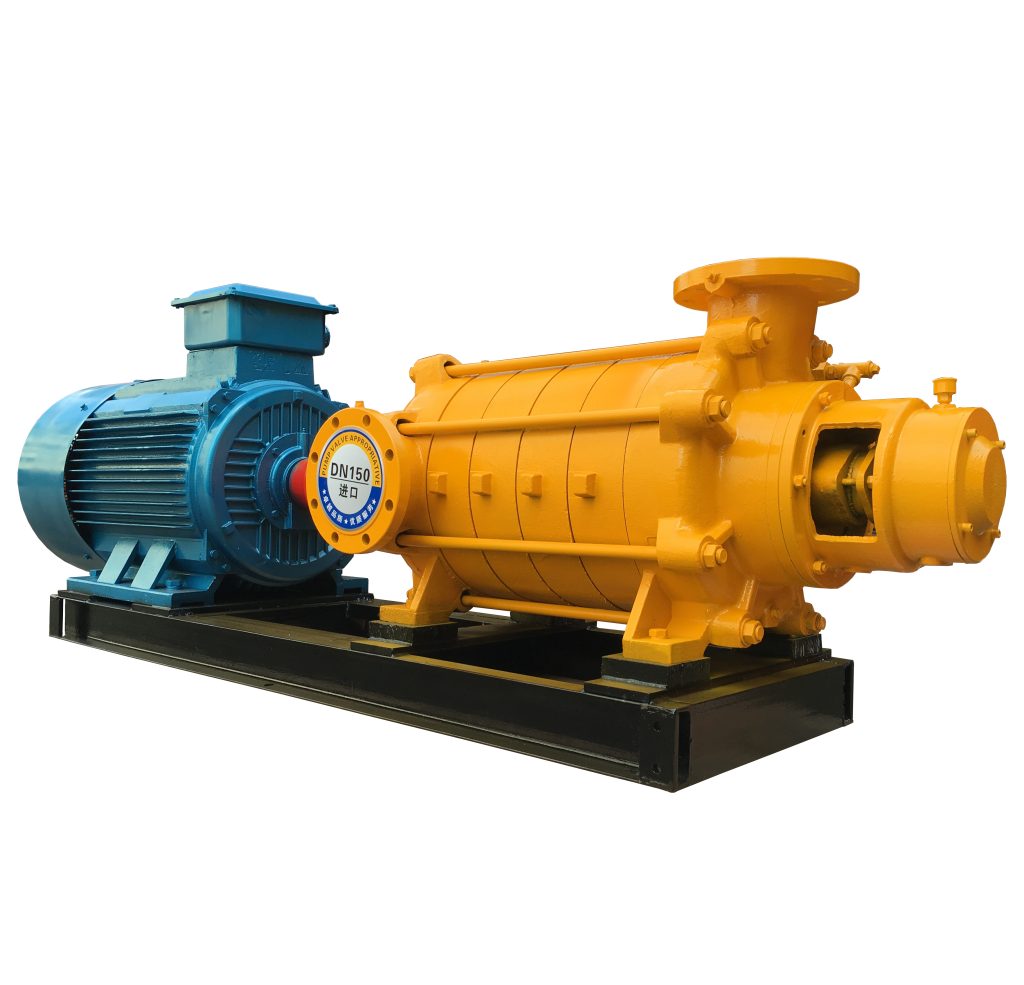
Product Overview
TSWA Series Horizontal Multistage Centrifugal Pump is engineered to deliver stable high-pressure water supply for industrial, municipal, and building systems.
It effectively solves problems such as:
- Insufficient pressure in long-distance pipelines
- High-rise water supply boosting
- Large-scale circulation systems requiring stable high head
The horizontal segmental multistage design ensures reliable pressure build-up while maintaining smooth continuous-duty operation.
Model Designation

Applications
- Building water supply systems requiring staged pressure boosting
- Industrial circulating water systems under controlled temperature conditions
- Boiler feed systems within allowable temperature limits
- Municipal water transfer stations
- Process water conveying where stable head is required
Engineering Advantages
- Horizontal multistage hydraulic configuration ensures gradual pressure rise with stable head output across duty range.
- Sectional casing structure improves axial load balance and simplifies maintenance access.
- Optimized impeller staging maintains hydraulic efficiency under rated flow conditions.
- Rigid shaft support structure enhances mechanical stability during continuous operation.
Hydraulic design optimization combined with simplified mechanical architecture ensures reliable clean water conveying within rated performance limits.
System Components
The TSWA horizontal multistage centrifugal pump mainly consists of:
- Pump casing (sectional type)
- Multistage impeller assembly
- Pump shaft
- Guide vanes
- Mechanical seal or packing seal
- Bearing housing
- Motor (direct coupling type)
Technical Parameters
Operating Conditions
- Flow rate: 3.2 – 12.5 m³/h
- Head: 12.5 – 32 m
- Power range: 0.75 – 4 kW
- Speed: 2900 rpm
- Liquid temperature: ≤ 80°C (standard)
- Working pressure: ≤ 1.6 MPa
Detailed parameter tables are provided below.
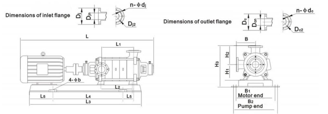
Installation Dimensions/Size
Outline Drawing

Pump Parts & Materials List
| Item No. | Coupling Name | Material | No. | Coupling Name | Material | Item No. | Coupling Name | Material | Item No. | Coupling Name | Material |
| 1 | Coupling | HT200 | 7 | Guide vane | HT200 | 13 | Balancing disc | HT200 | 19 | Right bearing gland | HT200 |
| 2 | Left bearing gland | HT200 | 8 | Middle section | HT200 | 14 | Packing body | HT200 | 20 | Left bearing gland | Q235 |
| 3 | Left bearing housing | HT200 | 9 | Last guide vane | HT200 | 15 | Right bearing housing | HT200 | 21 | Bearing | Tin bronze |
| 4 | Left packing gland | HT200 | 10 | Discharge section | HT200 | 16 | Right packing gland | HT200 | 22 | Left bearing bush | Q235 |
| 5 | Suction section | HT200 | 11 | Balancing section | HT200 | 17 | Right packing sleeve | Q235 | 23 | Left packing sleeve | Q235 |
| 6 | Impeller | HT200 | 12 | Balancing ring | HT200 | 18 | Right bearing bush | Q235 | 24 | Shaft | 45 or 2Cr13 |
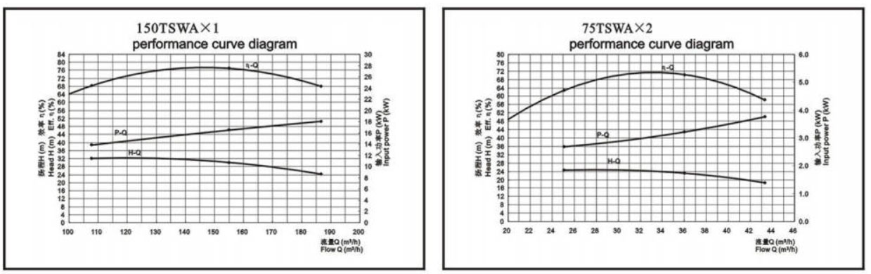
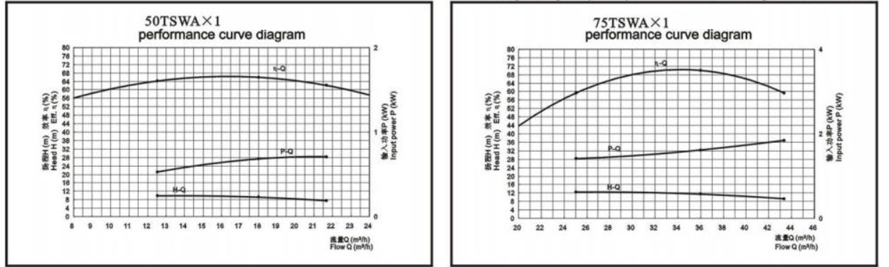
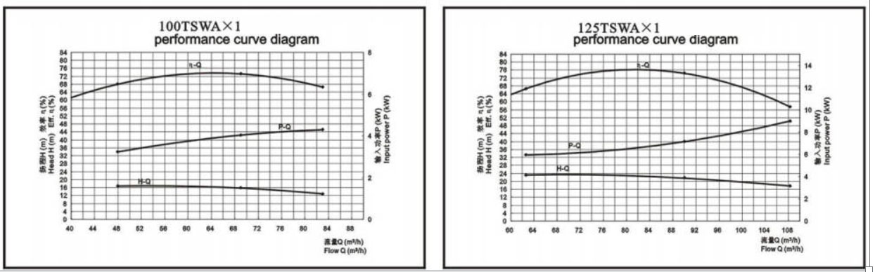
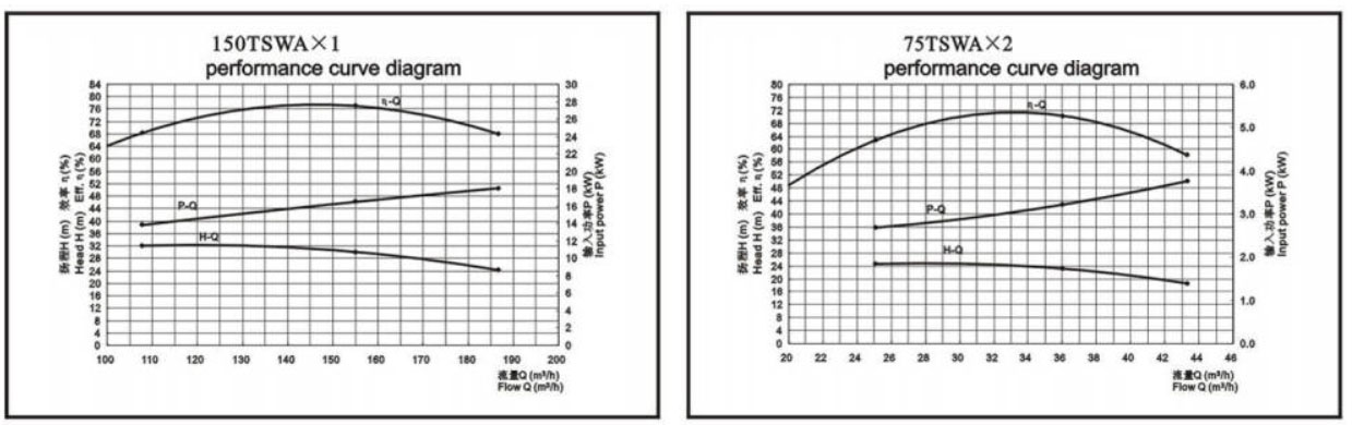
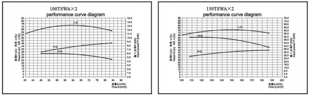
Performance Curves
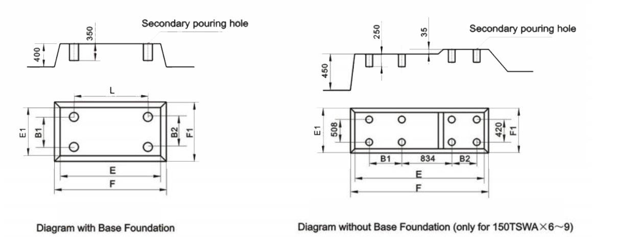
Installation Diagrams
Installation Dimensions
| Model | Stages | Pump Dimensions (H2=B) | Baseplate dimensions | Flange Dimensions | ||||||||||||
| L | L1 | L2 | B | H3 | L3 | L4 | L5 | B1 | B2 | 4-φb | D | D1 | Dn | n-φd | ||
| 50TSWA18-9.2*2 | 2 | 1087 | 160 | 145 | 230 | 480 | 901 | 600 | 33 | 335 | 430 | 4-φ25 | 160 | 125 | 50 | 4-φ18 |
| 50TSWA18-9.2*3 | 3 | 1152 | 225 | 210 | 230 | 480 | 901 | 600 | 33 | 335 | 430 | 4-φ25 | 160 | 125 | 50 | 4-φ18 |
| 50TSWA18-9.2*4 | 4 | 1237 | 290 | 275 | 230 | 480 | 974 | 640 | 128 | 375 | 430 | 4-φ25 | 160 | 125 | 50 | 4-φ18 |
| 50TSWA18-9.2*5 | 5 | 1377 | 355 | 340 | 230 | 490 | 1153 | 740 | 132 | 430 | 430 | 4-φ25 | 160 | 125 | 50 | 4-φ18 |
| 50TSWA18-9.2*6 | 6 | 1442 | 420 | 405 | 230 | 490 | 1153 | 740 | 197 | 430 | 430 | 4-φ25 | 160 | 125 | 50 | 4-φ18 |
| 50TSWA18-9.2*7 | 7 | 1547 | 485 | 470 | 230 | 490 | 1321 | 840 | 197 | 430 | 430 | 4-φ25 | 160 | 125 | 50 | 4-φ18 |
| 50TSWA18-9.2*8 | 8 | 1612 | 550 | 535 | 230 | 490 | 1321 | 840 | 262 | 430 | 430 | 4-φ25 | 160 | 125 | 50 | 4-φ18 |
| 50TSWA18-9.2*9 | 9 | 1677 | 615 | 600 | 230 | 490 | 1386 | 860 | 297 | 430 | 430 | 4-φ25 | 160 | 125 | 50 | 4-φ18 |
| 50TSWA18-9.2*10 | 10 | 1827 | 680 | 665 | 230 | 490 | 1593 | 900 | 362 | 430 | 430 | 4-φ25 | 160 | 125 | 50 | 4-φ18 |
| 50TSWA18-9.2*11 | 11 | 1930 | 745 | 730 | 230 | 490 | 1593 | 1000 | 427 | 430 | 430 | 4-φ25 | 160 | 125 | 50 | 4-φ18 |
| 50TSWA18-9.2*12 | 12 | 1957 | 810 | 795 | 230 | 490 | 1658 | 1200 | 462 | 430 | 430 | 4-φ25 | 160 | 125 | 50 | 4-φ18 |
| Model | Stages | Pump Dimensions (H2=B) | Baseplate dimensions | Flange Dimensions | ||||||||||||
| L | L1 | L2 | B | H3 | L3 | L4 | L5 | B1 | B2 | 4-φb | D | D1 | Dn | n-φd | ||
| 75TSWA36-11.5*2 | 2 | 1241 | 177 | 180 | 250 | 535 | 1046 | 690 | 89 | 410 | 475 | 4-φ25 | 195 | 160 | 80 | 4-φ18 |
| 75TSWA36-11.5*3 | 3 | 1361 | 257 | 260 | 250 | 545 | 1046 | 690 | 128 | 410 | 475 | 4-φ25 | 195 | 160 | 80 | 4-φ18 |
| 75TSWA36-11.5*4 | 4 | 1526 | 337 | 340 | 250 | 545 | 1284 | 830 | 171 | 475 | 475 | 4-φ25 | 195 | 160 | 80 | 4-φ18 |
| 75TSWA36-11.5*5 | 5 | 1606 | 417 | 420 | 250 | 545 | 1284 | 830 | 211 | 475 | 475 | 4-φ25 | 195 | 160 | 80 | 4-φ18 |
| 75TSWA36-11.5*6 | 6 | 1731 | 497 | 500 | 250 | 545 | 1488 | 980 | 245 | 475 | 475 | 4-φ25 | 195 | 160 | 80 | 4-φ18 |
| 75TSWA36-11.5*7 | 7 | 1811 | 577 | 580 | 250 | 545 | 1488 | 980 | 245 | 475 | 475 | 4-φ25 | 195 | 160 | 80 | 4-φ18 |
| 75TSWA36-11.5*8 | 8 | 1916 | 657 | 660 | 250 | 560 | 1653 | 1150 | 239 | 480 | 480 | 4-φ25 | 195 | 160 | 80 | 4-φ18 |
| 75TSWA36-11.5*9 | 9 | 1996 | 737 | 740 | 250 | 560 | 1653 | 1150 | 239 | 480 | 480 | 4-φ25 | 195 | 160 | 80 | 4-φ18 |
| 75TSWA36-11.5*10 | 10 | / | / | / | / | / | / | / | / | / | / | / | / | / | / | / |
| 75TSWA36-11.5*11 | 11 | / | / | / | / | / | / | / | / | / | / | / | / | / | / | / |
| Model | Stages | Pump Dimensions (H2=B) | Baseplate dimensions | Flange Dimensions | ||||||||||||
| L | L1 | L2 | B | H3 | L3 | L4 | L5 | B1 | B2 | 4-φb | D | D1 | Dn | n-φd | ||
| 100TSWA69-15.6*2 | 2 | 1575 | 255 | 200 | 310 | 610 | 1322 | 900 | 100 | 505 | 505 | 4-φ30 | 230 | 190 | 100 | 8-φ23 |
| 100TSWA69-15.6*3 | 3 | 1720 | 355 | 300 | 310 | 610 | 1322 | 900 | 149 | 505 | 505 | 4-φ30 | 230 | 190 | 100 | 8-φ23 |
| 100TSWA69-15.6*4 | 4 | 1885 | 455 | 400 | 310 | 610 | 1463 | 975 | 200 | 505 | 505 | 4-φ30 | 230 | 190 | 100 | 8-φ23 |
| 100TSWA69-15.6*5 | 5 | 2050 | 555 | 500 | 310 | 620 | 1701 | 1240 | 202 | 525 | 525 | 4-φ30 | 230 | 190 | 100 | 8-φ23 |
| 100TSWA69-15.6*6 | 6 | 2150 | 655 | 600 | 310 | 620 | 1701 | 1240 | 157 | 525 | 525 | 4-φ30 | 230 | 190 | 100 | 8-φ23 |
| 100TSWA69-15.6*7 | 7 | 2295 | 755 | 700 | 310 | 630 | 1959 | 1450 | 198 | 565 | 565 | 4-φ30 | 230 | 190 | 100 | 8-φ23 |
| 100TSWA69-15.6*8 | 8 | 2420 | 855 | 800 | 310 | 640 | 1959 | 1450 | 199 | 565 | 565 | 4-φ30 | 230 | 190 | 100 | 8-φ23 |
| 100TSWA69-15.6*9 | 9 | 2520 | 955 | 900 | 310 | 640 | 2059 | 1550 | 199 | 565 | 565 | 4-φ30 | 230 | 190 | 100 | 8-φ23 |
| 100TSWA69-15.6*10 | 10 | / | / | / | / | / | / | / | / | / | / | / | / | / | / | / |
| Model | Stages | Pump Dimensions (H2=B) | Baseplate dimensions | Flange Dimensions | ||||||||||||
| L | L1 | L2 | B | H3 | L3 | L4 | L5 | B1 | B2 | 4-φb | D | D1 | Dn | n-φd | ||
| 125TSWA90-21.6*2 | 2 | 1740 | 270 | 205 | 320 | 670 | 1312 | 990 | 220 | 500 | 500 | 4-φ30 | 270 | 220 | 125 | 8-φ25 |
| 125TSWA90-21.6*3 | 3 | 1890 | 370 | 305 | 320 | 670 | 1449 | 1000 | 230 | 500 | 500 | 4-φ30 | 270 | 220 | 125 | 8-φ25 |
| 125TSWA90-21.6*4 | 4 | 2060 | 470 | 405 | 320 | 680 | 1603 | 1100 | 240 | 520 | 520 | 4-φ30 | 270 | 220 | 125 | 8-φ25 |
| 125TSWA90-21.6*5 | 5 | 2250 | 570 | 505 | 320 | 695 | 1774 | 1170 | 270 | 570 | 520 | 4-φ30 | 270 | 220 | 125 | 8-φ25 |
| 125TSWA90-21.6*6 | 6 | 2420 | 670 | 605 | 320 | 725 | 2005 | 1260 | 305 | 630 | 520 | 4-φ30 | 270 | 220 | 125 | 8-φ25 |
| 125TSWA90-21.6*7 | 7 | 2520 | 770 | 705 | 320 | 725 | 2005 | 1260 | 305 | 630 | 520 | 4-φ30 | 270 | 220 | 125 | 8-φ25 |
| 125TSWA90-21.6*8 | 8 | 2670 | 870 | 805 | 320 | 725 | 2243 | 1430 | 305 | 630 | 570 | 4-φ30 | 270 | 220 | 125 | 8-φ25 |
| 125TSWA90-21.6*9 | 9 | 2770 | 970 | 905 | 320 | 725 | 2243 | 1430 | 305 | 630 | 520 | 4-φ30 | 270 | 220 | 125 | 8-φ25 |
| 125TSWA90-21.6*10 | 10 | / | / | / | / | / | / | / | / | / | / | / | / | / | / | / |
| Model | Stages | Pump Dimensions (H2=B) | Baseplate dimensions | Flange Dimensions | ||||||||||||
| L | L1 | L2 | B | H3 | L3 | L4 | L5 | B1 | B2 | 4-φb | D | D1 | Dn | n-φd | ||
| 150TSWA155-30*2 | 2 | 1964 | 236 | 237 | 350 | 720 | 1437 | 1000 | 80 | 720 | 575 | 4-φ30 | 280 | 240 | 150 | 8-φ23 |
| 150TSWA155-30*3 | 3 | 2234 | 350 | 352 | 350 | 735 | 1735 | 1165 | 148 | 735 | 675 | 4-φ30 | 280 | 240 | 150 | 8-φ23 |
| 150TSWA155-30*4 | 4 | 2399 | 465 | 467 | 350 | 745 | 1922 | 1260 | 215 | 745 | 675 | 4-φ30 | 280 | 240 | 150 | 8-φ23 |
| 150TSWA155-30*5 | 5 | 2664 | 580 | 582 | 350 | 780 | 2129 | 1470 | 212 | 780 | 765 | 4-φ30 | 280 | 240 | 150 | 8-φ23 |
| 150TSWA155-30*6 | 6 | 2829 | 695 | 697 | 350 | / | / | / | / | / | / | / | / | / | / | / |
| 150TSWA155-30*7 | 7 | 2944 | 810 | 812 | 350 | / | / | / | / | / | / | / | / | / | / | / |
| 150TSWA155-30*8 | 8 | 3019 | 925 | 927 | 350 | / | / | / | / | / | / | / | / | / | / | / |
| 150TSWA155-30*9 | 9 | 3224 | 1040 | 1042 | 350 | / | / | / | / | / | / | / | / | / | / | / |
How to Select Pump Model
Proper model selection should be based on:
- Required flow rate and target head within rated hydraulic range
- Medium type and temperature (≤ 80°C standard)
- System pressure requirements and allowable working pressure
- Installation configuration and pipeline diameter compatibility
- Motor power matching under continuous duty operation
Engineering Notes
- Pump foundation shall ensure alignment stability to prevent shaft misalignment.
- Suction conditions must prevent cavitation within allowable NPSH range.
- System piping should minimize hydraulic losses.
- Operation outside rated flow range may reduce hydraulic efficiency.
Compliance & Quality Assurance
Each TSWA pump is supplied with documented factory testing records, including:
- Hydraulic performance test verification
- Mechanical run test
- Material inspection and traceability
- Optional third-party inspection upon request
Safety Notice
- Do not operate under dry-running condition.
- Ensure proper suction priming before startup.
- Disconnect power supply before maintenance.
- Avoid operation beyond rated pressure limits.
OEM & Custom
This pump series supports engineered configuration and duty-based matching. Technical adjustments can be made according to system requirements and installation conditions.
Available options include:
- Motor voltage & frequency
- Mechanical seal type and configuration
- Wetted parts material selection
- Surface coating and corrosion protection
Configuration is determined based on duty point and project specifications.
FAQs
- Q1: Can the TSWA pump operate under VFD control?
Yes, provided motor compatibility and minimum flow requirements are maintained. - Q1:Can the TSWA pump be operated with a variable frequency drive (VFD)?
Available, subject to motor compatibility and minimum flow requirements. - Q2: What is the allowable working pressure?
Maximum working pressure is ≤ 1.6 MPa under standard configuration. - Q3: What sealing options are available?
Mechanical seal or packing seal depending on application requirement. - Q4: What liquid temperature is permitted?
Standard configuration allows ≤ 80°C. - Q5: What standards does the pump comply with?
Manufactured according to applicable industrial centrifugal pump standards. - Q6: How is hydraulic performance verified?
Each unit undergoes factory hydraulic performance testing before shipment.