Product Overview
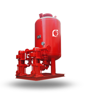
W-HY Automatic Fire Booster Unit is an intelligent fire pressure stabilizing and boosting system designed to maintain constant pipeline pressure in automatic fire protection networks.
It compensates for pressure fluctuations and leakage loss to ensure immediate fire system response readiness.
It is applied in sprinkler systems, hydrant systems, and building fire pipeline networks requiring continuous pressure stabilization.
Model Designation

Applications
- Closed-loop sprinkler systems with micro-leakage pressure drop
- High-rise building hydrant standby pressure systems
- Fire pipeline networks with long-distance pressure loss
- Facilities requiring automatic pressure compensation during standby
- Combined fire pump room pressure maintenance configuration
Engineering Advantages
- Integrated booster pump, pressure tank, and intelligent control system
- Automatic pressure sensing and start-stop logic control
- Small-flow compensation design preventing frequent fire pump activation
- Pressure tank buffering improves system stability
- Modular skid-mounted configuration simplifies installation
System Components
W-HY Fire Pressure Unit — Main Parts:
- Booster pump (vertical multistage type)
- Pressure tank
- Pressure transmitter
- Intelligent fire control cabinet
- Check valve and isolation valves
- Base frame and piping assembly
Technical Parameters
Service Conditions
Designed for fire standby pressure stabilization duty in fixed fire protection systems.
Operating Conditions
Flow rate: m³/h
Head: m
Power range: kW
Speed: rpm
Liquid temperature: ≤
Working pressure: ≤
Detailed parameter tables are provided below.
Installation & Dimensions
Installation Diagram
 Performance Data
|
|
|
Performance Parameters
| Item No. | Pressure Booster Model | Firefighting Pressure MPa P1 | Vertical Diaphragm Air Tank | Matching Pump | “Operating Weight (kg)” | Operating Pressure (MPa) | “Pressure Stabilizing Water Volume (L)” | ||||
| Model Specifications | Working Pressure Ratio | Firefighting Water Capacity (L) | Model | ||||||||
| Rated Capacity | Actual Volume | ||||||||||
| 1 | ZW(L)-I-X-7 | 0.1 | SQL800*0.6 | 0.60 | 300 | 319 | 25LG3-10*4 1.5KW | 1452 |
P1=0.10 Ps1=0.26
P2=0.23 Ps2=0.31 |
54 | |
| 2 | ZW(L)-I-Z-10 | 0.16 | SQL800*0.6 | 0.80 | 150 | 159 | 25LG3-10*4 1.5KW | 1428 |
P1=0.16 Ps1=0.26
P2=0.23 Ps2=0.31 |
70 | |
| 3 | ZW(L)-I-X-10 | 0.16 | SQL800*0.6 | 0.60 | 300 | 319 | 25LG3-10*5 1.5KW | 1474 |
P1=0.16 Ps1=0.36
P2=0.33 Ps2=0.42 |
52 | |
| 4 | ZW(L)-I-X-13 | 0.22 | SQL1000*0.6 | 0.76 | 300 | 329 | 25LG3-10*4 1.5KW | 2312 |
P1=0.22 Ps1=0.35
P2=0.32 Ps2=0.40 |
97 | |
| 5 | ZW(L)-XZ-10 | 0.16 | SQL1000*0.6 | 0.65 | 450 | 480 | 25LG3-10*4 1.5KW | 2312 |
P1=0.16 Ps1=0.33
P2=0.30 Ps2=0.38 |
86 | |
| 6 | ZW(L)-XZ-13 | 0.22 | SQL1000*0.6 | 0.67 | 450 | 452 | 25LG3-10*5 1.5KW | 2312 |
P1=0.22 Ps1=0.41
P2=0.38 Ps2=0.46 |
80 | |
| 7 | ZW(L)-II-Z- | A | 0.22-0.38 | SQL800*0.6 | 0.80 | 150 | 159 | 25LG3-10*6 2.2KW | 1452 |
P1=0.38 Ps1=0.53
P2=0.50 Ps2=0.60 |
61 |
| 8 | ZW(L)-II-Z- | B | 0.38-0.50 | SQL800*1.0 | 0.80 | 150 | 159 | 25LG3-10*8 2.2KW | 1513 |
P1=0.50 Ps1=0.68
P2=0.65 Ps2=0.75 |
51 |
| 9 | ZW(L)-II-Z- | C | 0.50-0.65 | SQL1000*1.6 | 0.85 | 150 | 206 | 25LG3-10*9 2.2KW | 1653 |
P1=0.65 Ps1=0.81
P2=0.78 Ps2=0.86 |
59 |
| 10 | ZW(L)-II-Z- | D | 0.65-0.85 | SQL1000*1.6 | 0.85 | 150 | 206 | 25LG3-10*11 3KW | 1701 |
P1=0.85 Ps1=1.04
P2=1.02 Ps2=1.10 |
57 |
| 11 | ZW(L)-II-Z- | E | 0.85-1.00 | SQL1000*1.6 | 0.85 | 150 | 206 | 25LG3-10*13 4KW | 1709 |
P1=1.00 Ps1=1.21
P2=1.19 Ps2=1.27 |
50 |
| Item No. | Pressure Booster Model | Firefighting Pressure MPa P1 | Vertical Diaphragm Air Tank | Matching Pump | “Operating Weight (kg)” | Operating Pressure (MPa) | “Pressure Stabilizing Water Volume (L)” | ||||
| Model Specifications | Working Pressure Ratio | Firefighting Water Capacity (L) | Model | ||||||||
| Rated Capacity | Actual Volume | ||||||||||
| 12 | ZW(L)-II-X- | A | 0.22-0.38 | SQL1000*0.6 | 0.78 | 300 | 302 | 25LG3-10*6 2.2KW | 2344 |
P1=0.38 Ps1=0.55
P2=0.52 Ps2=0.60 |
72 |
| 13 | ZW(L)-II-X- | B | 0.38-0.50 | SQL1000*1.0 | 0.78 | 300 | 302 | 25LG3-10*8 2.2KW | 2494 |
P1=0.50 Ps1=0.70
P2=0.67 Ps2=0.75 |
61 |
| 14 | ZW(L)-II-X- | C | 0.50-0.65 | SQL1000*1.6 | 0.78 | 300 | 302 | 25LG3-10*10 3KW | 2689 |
P1=0.65 Ps1=0.88
P2=0.86 Ps2=0.93 |
51 |
| 15 | ZW(L)-II-X- | D | 0.65-0.85 | SQL1000*1.6 | 0.85 | 300 | 355 | 25LG3-10*13 4KW | 2703 |
P1=0.85 Ps1=1.05
P2=1.02 Ps2=1.10 |
82 |
| 16 | ZW(L)-II-X- | E | 0.85-1.00 | SQL1000*1.6 | 0.88 | 300 | 355 | 25LG3-10*15 4KW | 2730 |
P1=1.00 Ps1=1.21
P2=1.19 Ps2=1.26 |
73 |
| 17 | ZW(L)-II-XZ- | A | 0.22-0.38 | SQL1200*0.6 | 0.80 | 450 | 474 | 25LG3-10*6 2.2KW | 3641 |
P1=0.38 Ps1=0.53
P2=0.50 Ps2=0.58 |
133 |
| 18 | ZW(L)-II-XZ- | B | 0.38-0.50 | SQL1200*1.0 | 0.80 | 450 | 474 | 25LG3-10*8 2.2KW | 3947 |
P1=0.50 Ps1=0.68
P2=0.65 Ps2=0.73 |
110 |
| 19 | ZW(L)-II-XZ- | C | 0.50-0.65 | SQL1200*1.6 | 0.80 | 450 | 474 | 25LG3-10*10 3KW | 3961 |
P1=0.65 Ps1=0.87
P2=0.84 Ps2=0.92 |
90 |
| 20 | ZW(L)-II-XZ- | D | 0.65-0.85 | SQL1200*1.6 | 0.80 | 450 | 474 | 25LG3-10*12 4KW | 4124 |
P1=0.85 Ps1=1.12
P2=1.09 Ps2=1.17 |
73 |
| 21 | ZW(L)-II-XZ- | E | 0.85-1.00 | SQL1200*1.6 | 0.80 | 450 | 474 | 25LG3-10*14 4KW | 4156 |
P1=1.00 Ps1=1.30
P2=1.27 Ps2=1.35 |
64 |
Notes:
|
|||||||||||
How to Select a Pump Model
- Determine system standby pressure and allowable pressure fluctuation range
- Calculate compensation flow based on leakage and testing discharge
- Select pressure tank volume according to system buffer requirement
- Verify control cabinet compatibility with fire alarm system
- Confirm pipeline rated pressure does not exceed unit working limit
Engineering Notes
- Pressure switch or transmitter calibration affects system stability
- Tank pre-charge pressure must match system static pressure
- Booster pump duty should remain within small-flow compensation range
- Avoid oversizing to prevent excessive pressure fluctuation
Compliance & Quality Assurance
- Factory pressure holding test for tank assembly
- Hydraulic performance test of booster pump
- Control cabinet functional test
- Electrical insulation resistance test
- Optional third-party inspection
Safety Notice
- Do not operate under dry-running condition
- Ensure correct pressure setting before commissioning
- Disconnect power before maintenance
- Avoid exceeding rated working pressure
OEM & Customization
This pump series supports engineered configuration and duty-based matching. Technical adjustments can be made according to system requirements and installation conditions.
Available options include:
• Motor voltage & frequency
• Pressure tank volume selection
• Control cabinet configuration
• Wetted parts material selection
• Surface coating and corrosion protection
Configuration is determined based on duty point and project specifications.
FAQs
Q: Can the booster unit operate under VFD control?
A: Yes, variable frequency configuration can be provided for precise pressure control.
Q: What is the allowable working pressure?
A: Maximum allowable working pressure is 1.6 MPa.
Q: How is pressure stabilization achieved?
A: Through automatic pressure sensing and small-flow pump compensation logic.
Q: Can the system prevent frequent main fire pump activation?
A: Yes, the unit compensates minor pressure loss to avoid unnecessary fire pump start.
Q: What type of pump is typically used in the unit?
A: Vertical multistage centrifugal pump is commonly used.
Q: Is the pressure tank mandatory?
A: Yes, it provides pressure buffering and reduces frequent pump cycling.
Q: What liquid temperature is allowable?
A: Maximum allowable liquid temperature is 80°C.