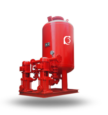
Product Overview
W(H)Y Fire Pressure Boosting & Stabilizing Equipment is an integrated fire water pressure maintenance system designed for automatic pressure stabilization and standby water supply in fire protection networks.
It maintains constant pipeline pressure, compensates for minor system leakage, and reduces unnecessary starting of the main fire pump.
It is widely used in high-rise buildings, commercial complexes, industrial plants, and municipal fire water supply systems.
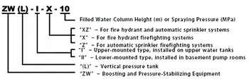
Model Designation
Applications
Typical Operating Applications
- Standby pressure maintenance for automatic sprinkler systems in high-rise buildings
- Pressure stabilization for fire hydrant and hose reel networks in commercial facilities
- Leakage compensation in industrial fire protection ring main systems
- Fire water pressure holding for warehouses and logistics centers
- Auxiliary pressure maintenance in municipal fire pipeline networks
- Automatic replenishment for fire water systems in hospitals, schools, and public buildings
Engineering Advantages
Structural Design Logic and Engineering Performance
- Integrated jockey pump, pressure vessel, control cabinet, and instrumentation provide compact skid-mounted installation.
- Automatic pressure sensing maintains network pressure within preset operating limits under standby conditions.
- Pressure compensation reduces frequent starting of the main fire pump, extending equipment service life.
- Stable standby pressure improves immediate system response during emergency fire demand.
- Modular configuration simplifies installation, commissioning, and maintenance.
System Components
W(H)Y Fire Pressure Boosting & Stabilizing Equipment Mainly Consists Of:
- Jockey pump assembly
- Pressure vessel
- Electrical control cabinet
- Pressure transmitter and pressure switches
- Check valves and isolation valves
- Base frame and interconnecting pipework
- Automatic control and monitoring system
Technical Specifications
Service Conditions
- Suitable medium: Clean water or fire water without abrasive particles
- Ambient temperature: 4°C to 40°C
- Relative humidity: ≤95%
- Installation altitude: ≤1000 m
- Indoor or protected outdoor installation
Operating Conditions
- Flow rate: 1–50 m³/h
- Head: 20–150 m
- Power range: 0.75–22 kW
- Speed: 2900 rpm
- Liquid temperature: ≤80°C
- Working pressure: ≤1.6 MPa
Detailed parameter tables are provided below.
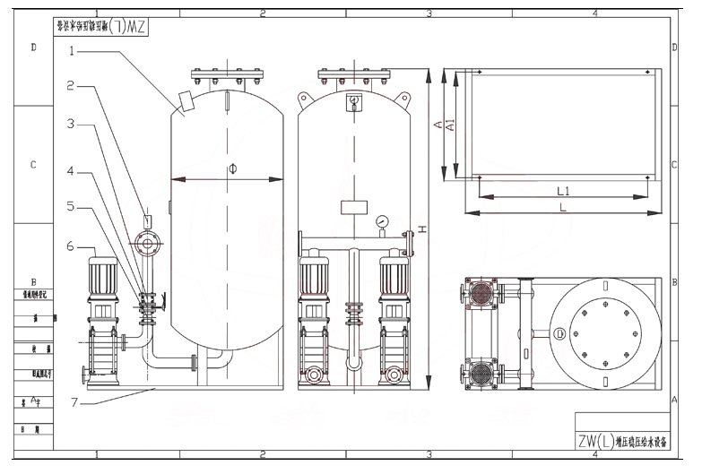
Installation & Dimensions
Outline Drawing
Performance Data
|
|
|
Performance Parameters
| No. | Booster & Pressure-Stabilizing Unit Model | Fire Pressure P1 (MPa) | Vertical Diaphragm Pressure Tank | Matched Pump | Operating Weight (kg) | Operating Pressure (MPa) | Pressure-Stabilizing Volume (L) | ||||
| Tank Model | Working Pressure Ratio | Fire Storage Volume (L) | Pump Model | ||||||||
| Rated Volume | Effective Volume | ||||||||||
| 1 | ZW(L)-I-X-7 | 0.1 | SQL800*0.6 | 0.60 | 300 | 319 | 25LG3-10*4 1.5 kW | 1452 | P1=0.10 Ps1=0.26 P2=0.23 Ps2=0.31 | 54 | |
| 2 | ZW(L)-I-Z-10 | 0.16 | SQL800*0.6 | 0.80 | 150 | 159 | 25LG3-10*4 1.5 kW | 1428 | P1=0.16 Ps1=0.26 P2=0.23 Ps2=0.31 | 70 | |
| 3 | ZW(L)-I-X-10 | 0.16 | SQL800*0.6 | 0.60 | 300 | 319 | 25LG3-10*5 1.5 kW | 1474 | P1=0.16 Ps1=0.36 P2=0.33 Ps2=0.42 | 52 | |
| 4 | ZW(L)-I-X-13 | 0.22 | SQL1000*0.6 | 0.76 | 300 | 329 | 25LG3-10*4 1.5 kW | 2312 | P1=0.22 Ps1=0.35 P2=0.32 Ps2=0.40 | 97 | |
| 5 | ZW(L)-XZ-10 | 0.16 | SQL1000*0.6 | 0.65 | 450 | 480 | 25LG3-10*4 1.5 kW | 2312 | P1=0.16 Ps1=0.33 P2=0.30 Ps2=0.38 | 86 | |
| 6 | ZW(L)-XZ-13 | 0.22 | SQL1000*0.6 | 0.67 | 450 | 452 | 25LG3-10*5 1.5 kW | 2312 | P1=0.22 Ps1=0.41 P2=0.38 Ps2=0.46 | 80 | |
| 7 | ZW(L)-II-Z- | A | 0.22-0.38 | SQL800*0.6 | 0.80 | 150 | 159 | 25LG3-10*6 2.2 kW | 1452 | P1=0.38 Ps1=0.53 P2=0.50 Ps2=0.60 | 61 |
| 8 | ZW(L)-II-Z- | B | 0.38-0.50 | SQL800*1.0 | 0.80 | 150 | 159 | 25LG3-10*8 2.2 kW | 1513 | P1=0.50 Ps1=0.68 P2=0.65 Ps2=0.75 | 51 |
| 9 | ZW(L)-II-Z- | C | 0.50-0.65 | SQL1000*1.6 | 0.85 | 150 | 206 | 25LG3-10*9 2.2 kW | 1653 | P1=0.65 Ps1=0.81 P2=0.78 Ps2=0.86 | 59 |
| 10 | ZW(L)-II-Z- | D | 0.65-0.85 | SQL1000*1.6 | 0.85 | 150 | 206 | 25LG3-10*11 3 kW | 1701 | P1=0.85 Ps1=1.04 P2=1.02 Ps2=1.10 | 57 |
| 11 | ZW(L)-II-Z- | E | 0.85-1.00 | SQL1000*1.6 | 0.85 | 150 | 206 | 25LG3-10*13 4 kW | 1709 | P1=1.00 Ps1=1.21 P2=1.19 Ps2=1.27 | 50 |
| No. | Booster & Pressure-Stabilizing Unit Model | Fire Pressure P1 (MPa) | Vertical Diaphragm Pressure Tank | Matched Pump | Operating Weight (kg) | Operating Pressure (MPa) | Pressure-Stabilizing Volume (L) | ||||
| Tank Model | Working Pressure Ratio | Fire Storage Volume (L) | Pump Model | ||||||||
| Rated Volume | Effective Volume | ||||||||||
| 12 | ZW(L)-II-X- | A | 0.22-0.38 | SQL1000*0.6 | 0.78 | 300 | 302 | 25LG3-10*6 2.2 kW | 2344 | P1=0.38 Ps1=0.55 P2=0.52 Ps2=0.60 | 72 |
| 13 | ZW(L)-II-X- | B | 0.38-0.50 | SQL1000*1.0 | 0.78 | 300 | 302 | 25LG3-10*8 2.2 kW | 2494 | P1=0.50 Ps1=0.70 P2=0.67 Ps2=0.75 | 61 |
| 14 | ZW(L)-II-X- | C | 0.50-0.65 | SQL1000*1.6 | 0.78 | 300 | 302 | 25LG3-10*10 3 kW | 2689 | P1=0.65 Ps1=0.88 P2=0.86 Ps2=0.93 | 51 |
| 15 | ZW(L)-II-X- | D | 0.65-0.85 | SQL1000*1.6 | 0.85 | 300 | 355 | 25LG3-10*13 4 kW | 2703 | P1=0.85 Ps1=1.05 P2=1.02 Ps2=1.10 | 82 |
| 16 | ZW(L)-II-X- | E | 0.85-1.00 | SQL1000*1.6 | 0.88 | 300 | 355 | 25LG3-10*15 4 kW | 2730 | P1=1.00 Ps1=1.21 P2=1.19 Ps2=1.26 | 73 |
| 17 | ZW(L)-II-XZ- | A | 0.22-0.38 | SQL1200*0.6 | 0.80 | 450 | 474 | 25LG3-10*6 2.2 kW | 3641 | P1=0.38 Ps1=0.53 P2=0.50 Ps2=0.58 | 133 |
| 18 | ZW(L)-II-XZ- | B | 0.38-0.50 | SQL1200*1.0 | 0.80 | 450 | 474 | 25LG3-10*8 2.2 kW | 3947 | P1=0.50 Ps1=0.68 P2=0.65 Ps2=0.73 | 110 |
| 19 | ZW(L)-II-XZ- | C | 0.50-0.65 | SQL1200*1.6 | 0.80 | 450 | 474 | 25LG3-10*10 3 kW | 3961 | P1=0.65 Ps1=0.87 P2=0.84 Ps2=0.92 | 90 |
| 20 | ZW(L)-II-XZ- | D | 0.65-0.85 | SQL1200*1.6 | 0.80 | 450 | 474 | 25LG3-10*12 4 kW | 4124 | P1=0.85 Ps1=1.12 P2=1.09 Ps2=1.17 | 73 |
| 21 | ZW(L)-II-XZ- | E | 0.85-1.00 | SQL1200*1.6 | 0.80 | 450 | 474 | 25LG3-10*14 4 kW | 4156 | P1=1.00 Ps1=1.30 P2=1.27 Ps2=1.35 | 64 |
Note:
|
|||||||||||
How to Select a Pump Model
- Determine standby replenishment flow according to system leakage volume.
- Calculate required pressure based on the highest fire terminal elevation.
- Select pressure vessel capacity according to pipeline volume and allowable cycling frequency.
- Verify motor power according to duty point and starting frequency.
- Confirm electrical supply, installation space, and control interface requirements.
Engineering Notes
- This equipment is intended for standby pressure maintenance only and is not the primary fire pump.
- The main fire pump shall automatically start when significant pressure drop occurs.
- Pressure vessel pre-charge shall be set according to pump cut-in pressure.
- Optional dual power supply and remote monitoring are available for critical systems.
- Commissioning shall comply with local fire protection regulations.
Compliance & Quality Assurance
- Hydraulic performance test for each pump unit
- Pressure vessel hydrostatic pressure test
- Electrical control cabinet functional verification
- Pressure switch and transmitter calibration
- Material traceability for pressure-bearing components
- Optional third-party inspection and factory acceptance test
Safety Notice
- Do not operate under dry-running condition.
- Ensure the suction line is fully primed before startup.
- Disconnect power before maintenance or inspection.
- Periodically verify automatic start-stop functionality.
OEM & Customization
This pump series supports engineered configuration and duty-based matching. Technical adjustments can be made according to system requirements and installation conditions.
Available options include:
- Motor voltage & frequency
- Pressure vessel capacity and material
- Mechanical seal type and configuration
- Control panel communication protocol
- Surface coating and corrosion protection
Configuration is determined based on duty point and project specifications.
FAQs
Q: Can the system operate under automatic pressure control?
A: Yes, the jockey pump starts and stops automatically based on preset pressure settings.
Q: What is the maximum allowable working pressure?
A: The standard maximum working pressure is 1.6 MPa.
Q: Is VFD control available?
A: Yes, variable frequency control is available upon request.
Q: What liquid can the system handle?
A: Clean water and treated fire water without abrasive solids.
Q: Can the pressure vessel size be customized?
A: Yes, vessel capacity can be selected according to system requirements.
Q: Does the equipment support BMS or SCADA integration?
A: Yes, optional communication modules are available.
Q: Which standards can the equipment comply with?
A: It can be configured according to local fire protection regulations and project specifications.