Product Overview
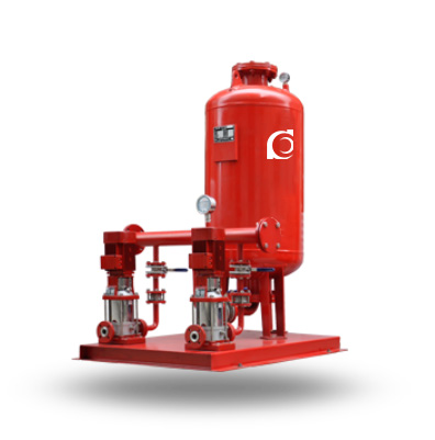
The ZW(L) Fire Pressure Stabilizing Water Supply System is a pressure boosting and stabilization solution specifically designed for firefighting water supply applications, built in strict compliance with GB 6245-2006 and NFPA 20 standards. The system is designed to address the issue of insufficient static pressure at the most unfavorable point in temporary high-pressure firefighting water supply systems, particularly when elevated firefighting water tanks cannot provide the required pressure. This unit serves as a dedicated fire pressure boosting and stabilization device, ensuring the stability and continuity of firefighting water pressure.
Model Designation
-HY LG Fire & Water Supply Pressure Stabilizing Set 1")
Key Features
- The ZW(L) Fire Pressure Stabilizing Water Supply System uses high-efficiency and stable pumps to provide continuous water flow and pressure for the system.
- The unit adopts a modular design for easy installation and maintenance, ensuring the system operates efficiently and stably.
- Pneumatic pumps provide stable pressure output, suitable for low-maintenance and high-efficiency applications.
Engineering Summary
The ZW(L) system combines pressure boosting and stabilization into a single integrated unit, ensuring the stability of the firefighting system. The system compensates for low water demand and normal pipeline leakage, maintaining the required pressure level during standby conditions, providing reliable pressure support for firefighting preparedness.
Applications
The system is widely used in multi-story and high-rise buildings for:
-
Fire hydrant water supply systems
-
Wet automatic sprinkler systems
-
Firefighting and domestic water supply systems
This system is designed for continuous pressure maintenance in firefighting pipelines and rapid response, ensuring reliability during firefighting operations.
System Configuration
-
SQL Series Diaphragm Pressure Tank: For continuous pressure maintenance.
-
Fire Pressure Stabilizing Pump: Works with the pressure tank to ensure stable operation.
-
Electrical Control Cabinet: Integrated control and monitoring system for automatic operation.
-
Measurement and Monitoring Instruments: Real-time monitoring of pressure and water flow to ensure system stability.
-
Related Pipes and Connectors: Includes all necessary connections and installation accessories.
System Components
-
Diaphragm Pressure Tank: Stores and regulates water pressure to ensure continuous supply.
-
Pressure Stabilizing Pump: Maintains system pressure to prevent fluctuations.
-
Electrical Control System: Responsible for automatic start/stop and real-time monitoring.
Design Fundamentals
The system adopts an integrated packaging configuration, with the pressure stabilizing pump directly coupled to the diaphragm pressure tank. The modular design facilitates on-site installation and integration. The system operates automatically through preset pressure logic, ensuring efficient and stable firefighting water supply.
Selection and Operational Principles
-
Selection Principles: Choose the appropriate pump type and supporting equipment based on the system’s design flow rate and required pressure.
-
Operational Principles: Ensure efficient operation and reliable emergency response, with regular checks and maintenance to ensure long-term stability.
Demand Applications
Suitable for firefighting systems requiring stable water pressure and continuous water supply, especially providing reliable backup water sources during power failures.
Intermittent Applications
Suitable for applications requiring intermittent pressurization, such as temporary firefighting water supply systems during off-peak hours.
Operational Principles
The system ensures stable operation and automatically adjusts based on pressure changes to meet firefighting needs while maintaining long-term stable operation.
Technical Service
-
Flow Range: 10–800 L/s
-
Pressure Range: 0.2–2.2 MPa
-
Rated Speed: 1500 / 1800 / 2400 rpm
-
Ambient Temperature: –15°C to +55°C
-
Atmospheric Pressure: ≥90 kPa
Technical Specifications
-
Rated Working Pressure of SQL Diaphragm Pressure Tank: 0.6 MPa / 1.0 MPa / 1.6 MPa
-
Effective Fire Water Storage Capacity of SQL Diaphragm Tank: ≥150L / 300L / 450L
-
Effective Pressure Stabilizing Water Volume: ≥50L
-
Pressure Difference for Buffer Water Volume: 0.02–0.03 MPa
-
Pressure Difference for Stabilizing Water Volume: 0.05–0.06 MPa
-
Operating Temperature Range: 0.6°C to 40°C
Service Conditions
-
Ambient Temperature: 5°C to 40°C
-
Water Source Requirements: Suitable for high-position water tanks or bottom-level water pools.
Environmental Requirements
The equipment operates stably under normal temperature and humidity conditions, suitable for most environments.
Electric Control Functions
The equipment is equipped with both automatic and manual control functions, and can be integrated with the firefighting control center to ensure rapid system activation during emergencies.
Operating Instructions
The operating system is user-friendly, with detailed operation and maintenance manuals to ensure the equipment runs efficiently and remains stable.
Installation & Dimensions
Installation Diagram
-HY LG Fire & Water Supply Pressure Stabilizing Set 2")
Performance Data
|
|
|
Performance Parameters
| No. | Booster Unit Model | Fire Pressure P1 (MPa) | Vertical Diaphragm Pressure Tank | Matched Pump | Operating Weight (kg) | Operating Pressure (MPa) | Stabilizing Volume (L) | ||||
| Tank Model | Pressure Ratio | Fire Storage Volume (L) | Pump Model | ||||||||
| Rated Volume | Actual Volume | ||||||||||
| 1 | ZW(L)-I-X-7 | 0.10 | SQL800×0.6 | 0.60 | 300 | 319 | 25LG3-10×4 1.5 kW | 1452 | P1=0.10 Ps1=0.26 P2=0.23 Ps2=0.31 | 54 | |
| 2 | ZW(L)-I-Z-10 | 0.16 | SQL800×0.6 | 0.80 | 150 | 159 | 25LG3-10×4 1.5 kW | 1428 | P1=0.16 Ps1=0.26 P2=0.23 Ps2=0.31 | 70 | |
| 3 | ZW(L)-I-X-10 | 0.16 | SQL800×0.6 | 0.60 | 300 | 319 | 25LG3-10×5 1.5 kW | 1474 | P1=0.16 Ps1=0.36 P2=0.33 Ps2=0.42 | 52 | |
| 4 | ZW(L)-I-X-13 | 0.22 | SQL1000×0.6 | 0.76 | 300 | 329 | 25LG3-10×4 1.5 kW | 2312 | P1=0.22 Ps1=0.35 P2=0.32 Ps2=0.40 | 97 | |
| 5 | ZW(L)-XZ-10 | 0.16 | SQL1000×0.6 | 0.65 | 450 | 480 | 25LG3-10×4 1.5 kW | 2312 | P1=0.16 Ps1=0.33 P2=0.30 Ps2=0.38 | 86 | |
| 6 | ZW(L)-XZ-13 | 0.22 | SQL1000×0.6 | 0.67 | 450 | 452 | 25LG3-10×5 1.5 kW | 2312 | P1=0.22 Ps1=0.41 P2=0.38 Ps2=0.46 | 80 | |
| 7 | ZW(L)-II-Z- | A | 0.22–0.38 | SQL800×0.6 | 0.80 | 150 | 159 | 25LG3-10×6 2.2 kW | 1452 | P1=0.38 Ps1=0.53 P2=0.50 Ps2=0.60 | 61 |
| 8 | ZW(L)-II-Z- | B | 0.38–0.50 | SQL800×1.0 | 0.80 | 150 | 159 | 25LG3-10×8 2.2 kW | 1513 | P1=0.50 Ps1=0.68 P2=0.65 Ps2=0.75 | 51 |
| 9 | ZW(L)-II-Z- | C | 0.50–0.65 | SQL1000×1.6 | 0.85 | 150 | 206 | 25LG3-10×9 2.2 kW | 1653 | P1=0.65 Ps1=0.81 P2=0.78 Ps2=0.86 | 59 |
| 10 | ZW(L)-II-Z- | D | 0.65–0.85 | SQL1000×1.6 | 0.85 | 150 | 206 | 25LG3-10×11 3 kW | 1701 | P1=0.85 Ps1=1.04 P2=1.02 Ps2=1.10 | 57 |
| 11 | ZW(L)-II-Z- | E | 0.85–1.00 | SQL1000×1.6 | 0.85 | 150 | 206 | 25LG3-10×13 4 kW | 1709 | P1=1.00 Ps1=1.21 P2=1.19 Ps2=1.27 | 50 |
| No. | Booster Unit Model | Fire Pressure P1 (MPa) | Vertical Diaphragm Pressure Tank | Matched Pump | Operating Weight (kg) | Operating Pressure (MPa) | Stabilizing Volume (L) | ||||
| Tank Model | Pressure Ratio | Fire Storage Volume (L) | Pump Model | ||||||||
| Rated Volume | Actual Volume | ||||||||||
| 12 | ZW(L)-II-X- | A | 0.22–0.38 | SQL1000×0.6 | 0.78 | 300 | 302 | 25LG3-10×6 2.2 kW | 2344 | P1=0.38 Ps1=0.55 P2=0.52 Ps2=0.60 | 72 |
| 13 | ZW(L)-II-X- | B | 0.38–0.50 | SQL1000×1.0 | 0.78 | 300 | 302 | 25LG3-10×8 2.2 kW | 2494 | P1=0.50 Ps1=0.70 P2=0.67 Ps2=0.75 | 61 |
| 14 | ZW(L)-II-X- | C | 0.50–0.65 | SQL1000×1.6 | 0.78 | 300 | 302 | 25LG3-10×10 3 kW | 2689 | P1=0.65 Ps1=0.88 P2=0.86 Ps2=0.93 | 51 |
| 15 | ZW(L)-II-X- | D | 0.65–0.85 | SQL1000×1.6 | 0.85 | 300 | 355 | 25LG3-10×13 4 kW | 2703 | P1=0.85 Ps1=1.05 P2=1.02 Ps2=1.10 | 82 |
| 16 | ZW(L)-II-X- | E | 0.85–1.00 | SQL1000×1.6 | 0.88 | 300 | 355 | 25LG3-10×15 4 kW | 2730 | P1=1.00 Ps1=1.21 P2=1.19 Ps2=1.26 | 73 |
| 17 | ZW(L)-II-XZ- | A | 0.22–0.38 | SQL1200×0.6 | 0.80 | 450 | 474 | 25LG3-10×6 2.2 kW | 3641 | P1=0.38 Ps1=0.53 P2=0.50 Ps2=0.58 | 133 |
| 18 | ZW(L)-II-XZ- | B | 0.38–0.50 | SQL1200×1.0 | 0.80 | 450 | 474 | 25LG3-10×8 2.2 kW | 3947 | P1=0.50 Ps1=0.68 P2=0.65 Ps2=0.73 | 110 |
| 19 | ZW(L)-II-XZ- | C | 0.50–0.65 | SQL1200×1.6 | 0.80 | 450 | 474 | 25LG3-10×10 3 kW | 3961 | P1=0.65 Ps1=0.87 P2=0.84 Ps2=0.92 | 90 |
| 20 | ZW(L)-II-XZ- | D | 0.65–0.85 | SQL1200×1.6 | 0.80 | 450 | 474 | 25LG3-10×12 4 kW | 4124 | P1=0.85 Ps1=1.12 P2=1.09 Ps2=1.17 | 73 |
| 21 | ZW(L)-II-XZ- | E | 0.85–1.00 | SQL1200×1.6 | 0.80 | 450 | 474 | 25LG3-10×14 4 kW | 4156 | P1=1.00 Ps1=1.30 P2=1.27 Ps2=1.35 | 64 |
| Note: 1) P1 – Inflation pressure of the diaphragm tank (required fire pressure) (MPa); P2 – Fire pump start pressure (MPa); Ps1 – Booster–stabilizing pump start pressure (MPa); Ps2 – Booster–stabilizing pump stop pressure (MPa). 2) Items No.1–6 are Type I Units, generally installed in high-level tank rooms (most unfavorable hydrant lower than the Unit). 3) Items No.7–21 are Type II Units, generally installed in fire pump rooms or water tank rooms. The corresponding fire pressure ranges and matched pumps are for selection reference. 4) The listed pump models are based on Chaodun Pump Factory products. Equivalent pumps from other manufacturers may be selected according to required flow and head. |
|||||||||||
Operating Manual
1. Product Overview
This Booster Pressure Stabilizing Equipment is designed and developed according to the Ministry of Construction of the People’s Republic of China’s [1996] 108 document from August 1996, in compliance with the specifications of 98S205 (formerly 98S176).
This equipment is specifically designed to address the issue of high-level fire water tanks in temporary high-pressure fire water supply systems where the set height does not meet the required conditions. It provides a specialized booster pressure stabilizing solution for firefighting applications (hereinafter referred to as “the equipment”).
This equipment is suitable for firefighting and domestic water supply systems, such as fire hydrant water supply systems and wet automatic sprinkler systems, in multi-story and high-rise construction projects requiring pressurization facilities.
2. Equipment and Principle
The equipment consists of an SQL air pressure water tank, XBD-GDL multi-stage fire hydrant pump, electrical control cabinet, instruments, pipeline accessories, and other components.
The design adheres to the technical standards outlined in the “Fire Protection Design Code for Civil Buildings” (GB50045-95) and the “Air Pressure Water Supply Design Code” (CECS76:95).
The working principle of this equipment is to control the pump operation by setting the P1, P2, Ps1, and Ps2 operating pressures, thereby achieving both pressure boosting and stabilization functions.
3. P1 Pressure Control
The required firefighting pressure, P1, at the adverse points in the system is calculated and serves as the charging pressure for the air pressure water tank. Based on this, P2, Ps1, and Ps2 are set to control the operation of the pressure-stabilizing pump.
The calculation of firefighting pressure P1 varies depending on the system type (such as fire hydrant systems or automatic sprinkler systems). This includes pipe system pressure losses along the route and at specific points, as well as the pressure required by the water nozzle.
4.Functions & Electrical Control
The equipment must fulfill two primary functions:
-
To maintain the required firefighting pressure at the adverse points in the fire water supply system.
-
To ensure that the air pressure water tank always stores enough firefighting water for 30 seconds. The equipment operates by controlling the pump using set pressures (P1, P2, Ps1, Ps2) to achieve pressure boosting and stabilization.
The electrical control system has both automatic and manual functions, is networked with the fire control center or fire pump room, and supports the alternating operation of two pressure-stabilizing pumps.
The system also includes a maintenance mode, allowing seamless switching between pumps if one fails, ensuring continuous operation of the equipment.
5. Equipment and Maintenance
The equipment is available in various configurations: mounted top (I), mounted bottom (II), vertical (L), and horizontal (W) types, which can be selected based on specific needs.
Firefighting systems can be configured with fire hydrant systems (X), automatic sprinkler systems (Z), or a combination of both (XZ).
Regular maintenance is essential to ensure reliable long-term operation. After approximately 2500 hours of operation, the equipment should undergo periodic inspection, with key components such as seals, oil seals, and shaft sleeves being replaced as necessary.
OEM & Custom
Chaodun Pump provides customized solutions for W-HY LG pressure stabilizing equipment, including tank size, control parameters, and pump configuration. We also offer integrated system designs for hydrant and sprinkler networks to meet specific building codes and international fire protection standards.
FAQs
- Q1: What is the W-HY LG Pressure Boosting & Stabilizing Equipment used for?
It is used for maintaining steady water pressure in fire hydrant and sprinkler systems of multi-story or high-rise buildings. - Q2: Can I customize the tank size or control system?
Yes, we provide OEM/ODM customization for air tank volume, pump specifications, and control cabinet design. - Q3: What are the main components?
The system includes a diaphragm air tank, booster pump, electric control box, gauges, and connecting valves. - Q4: What is the working pressure range?
It supports 0.1–1.0 MPa, suitable for various fire system configurations. - Q5: Does it meet fire safety regulations?
Yes, it complies with GB50045-95 and CECS76:95 fire protection design codes. - Q6: What’s the benefit of the diaphragm tank design?
It reduces energy loss, ensures quick pressure recovery, and minimizes maintenance requirements. - Q7: Can you provide international documentation?
Yes, Chaodun Pump supplies detailed datasheets, test reports, and compliance certificates for export projects.