Product Overview
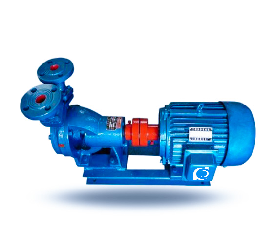
W Single-Stage Cantilever Vortex Pump is a horizontal, single-stage, single-suction vortex centrifugal pump designed for handling liquids containing solids, fibers, and suspended impurities without clogging.
It solves blockage, entanglement, and solid-handling limitations commonly encountered in conventional centrifugal pumps.
It is applied in wastewater transfer, industrial slurry handling, chemical process drainage, and solid-laden liquid conveying systems.
Model Designation

Applications
Typical Operating Conditions
- Municipal wastewater containing suspended solids
- Industrial slurry with fibrous impurities
- Food processing waste liquid transfer
- Chemical drainage with sediment particles
- Mining process tailings liquid handling
Engineering Advantages
Structural Logic & Engineering Result
- Vortex impeller recessed design minimizes direct contact between solids and impeller, reducing clogging risk.
- Large flow passage casing geometry enhances solid passing capability.
- Cantilever shaft design without submerged bearing improves maintenance accessibility.
- Single-stage hydraulic structure ensures stable flow and predictable performance curve.
System Components
W Single-Stage Cantilever Vortex Pump :
- Pump casing
- Vortex impeller
- Pump shaft
- Bearing housing
- Mechanical seal / Packing seal
- Coupling
- Base frame
Technical Specifications
Service Conditions
Suitable for liquids containing soft solids, fibers, and suspended particles without severe abrasion.
Operating Conditions
- Flow Rate: 0.72 – 14.4 m³/h
- Head: 20 – 120 m
- Power Range: 0.75 – 11 kW
- Speed: 2900 rpm
- Liquid Temperature: ≤ 80°C
- Working Pressure: ≤ 1.0 MPa
Detailed parameter tables are provided below.
Specifications & Installation
Outline Drawing

Performance Data
| 1 | Pump casing |
| 2 | Pump cover |
| 3 | Impeller |
| 4 | Bracket assembly |
| 5 | Pump shaft |
| 6 | Jaw-type flexible coupling |
| 7 | Special cartridge mechanical seal assembly |
Performance Parameters
| Model | Flow Rate (m³/h) | Head (m) | Voltage (V) | Speed (r/min) | Power (kW) |
| 20W-20 (single-stage) | 0.72 | 20 | 220/380 | 2900 | 0.75 |
| 20W-65 (single-stage) | 0.72 | 65 | 380 | 2900 | 2.2 |
| 25W-25 (single-stage) | 1.44 | 25 | 220/380 | 2900 | 0.75 |
| 25W-70 (single-stage) | 1.44 | 70 | 380 | 2900 | 3 |
| 32W-30 (single-stage) | 2.88 | 30 | 380 | 2900 | 1.5 |
| 32W-75 (single-stage) | 2.88 | 72 | 380 | 2900 | 4 |
| 32W-120 (single-stage) | 2.88 | 120 | 380 | 2900 | 5.5 |
| 40W-40 (single-stage) | 5.4 | 40 | 380 | 2900 | 4 |
| 40W-90 (single-stage) | 5.4 | 90 | 380 | 2900 | 7.5 |
| 50W-45 (single-stage) | 9 | 45 | 380 | 2900 | 5.5 |
| 65W-50 (single-stage) | 14.4 | 50 | 380 | 2900 | 11 |
How to Select a Pump Model
- Determine required flow rate and system head based on pipeline resistance calculation.
- Confirm maximum solid particle size and fiber content.
- Evaluate liquid density and viscosity for motor power correction.
- Check installation layout and shaft orientation requirement.
- Select sealing configuration according to leakage tolerance and medium characteristics.
Engineering Notes
- Vortex impeller clearance must be verified for large solid applications.
- Avoid operation far right of performance curve to prevent overload.
- Shaft overhang design requires correct alignment to reduce vibration.
- For abrasive media, consider hardened material configuration.
- Proper foundation rigidity improves bearing life.
Compliance & Quality Assurance
- Hydraulic performance test per ISO 9906
- Factory pressure casing test
- Dynamic balance test of impeller
- Material certification traceability
- Optional third-party inspection available
Safety Notice
- Do not operate under dry-running condition
- Ensure suction line is free from air blockage before startup
- Disconnect power before maintenance
- Do not exceed allowable working pressure
OEM & Custom
This pump series supports engineered configuration and duty-based matching. Technical adjustments can be made according to system requirements and installation conditions.
Available options include:
• Motor voltage & frequency
• Seal type (mechanical seal / packing seal)
• Impeller material upgrade
• Anti-corrosion coating
Configuration is determined based on duty point and project specifications.
FAQs
Q1: What is the maximum allowable solid size?
A: Depends on model size and impeller clearance; typically up to 60–80% of discharge diameter.
Q2: Can the pump operate under VFD control?
A: Yes, provided minimum flow and motor cooling requirements are maintained.
Q3: What sealing options are available?
A: Mechanical seal and packing seal are standard configurations.
Q4: What is the allowable working pressure?
A: Maximum working pressure is ≤1.0 MPa.
Q5: Is the pump suitable for fibrous wastewater?
A: Yes, vortex structure minimizes fiber entanglement.
Q6: Can abrasive-resistant materials be selected?
A: Yes, hardened alloys or wear-resistant materials can be configured.
Q7: Does the pump require priming?
A: Yes, standard configuration requires flooded suction or priming before startup.