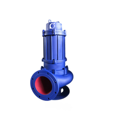
Product Overview
WQ / QW Submersible Non-Clog Sewage Pump is a submersible centrifugal pump with non-clog hydraulic design, developed for direct submerged operation in wastewater and drainage systems.
It eliminates suction limitations and priming requirements in drainage systems where liquid levels fluctuate or installation space is restricted.
It is suitable for municipal sewage stations, industrial wastewater pits, building basements, stormwater drainage, and emergency flood control applications.
Model Designation

Applications
- Underground sewage collection wells with automatic level control
- Industrial wastewater discharge containing suspended solids
- Basement drainage in residential and commercial buildings
- Stormwater pumping stations during heavy rainfall
- Construction site and temporary drainage systems
Engineering Advantages
• Fully submersible structure eliminates suction lift constraints and simplifies installation.
• Non-clog impeller with optimized flow passage improves solid-passing capability.
• Double mechanical seal configuration enhances reliability under continuous wastewater duty.
• Integrated motor and pump shaft structure ensures compact installation and stable alignment.
• Thermal protector and moisture detection options improve operational safety in submerged conditions.
System Components
WQ / QW Submersible Non-Clog Sewage Pump mainly includes:
- Submersible motor assembly
- Pump casing and volute chamber
- Non-clog impeller
- Double mechanical seal system
- Shaft and bearing assembly
- Cable sealing and waterproof structure
Technical Specifications
Service Conditions
- Suitable for sewage or wastewater containing solid particles and short fibers within allowable limits.
- Installation must ensure complete submersion of motor during operation.
Operating Conditions
- Flow rate: 7–2650 m³/h
- Head: 7–60 m
- Power range: 0.55–250 kW
- Speed: 740 / 980 / 1450 / 2900 rpm
- Liquid temperature: ≤ 40°C (standard)
- Working pressure: ≤ 1.0 MPa
Detailed parameter tables are provided below.
Installation & Dimensions
Outline Drawing

Performance Data
|
No.
|
Name
|
No.
|
Name
|
No.
|
Name
|
No.
|
Name
|
|
1
|
Signal Cable
|
6
|
Upper Bearing Seat
|
11
|
Oil-Water Probe
|
16
|
Impeller Bolt
|
|
2
|
Motor Lead Wire
|
7
|
Motor Housing
|
12
|
Oil Chamber
|
17
|
Impeller
|
|
3
|
Terminal Box
|
8
|
Stator
|
13
|
Mechanical Seal
|
18
|
Seal Ring
|
|
4
|
Motor Cover
|
9
|
Shaft (Rotor)
|
14
|
Rear Cover Plate
|
19
|
Base Plate
|
|
5
|
Bearing
|
10
|
Bearing
|
15
|
Pump Body
|
Outline Drawing(2)

Performance Parameters
|
Model
|
Port Size
|
Flow Rate
|
Head
|
Speed
|
Power
|
Efficiency
|
A
|
B
|
C
|
D
|
H
|
Auto Coupler
|
|
mm
|
(m3/h)
|
(M)
|
(r/min)
|
(kw)
|
(%)
|
|||||||
|
25-7-8-0.55
|
25
|
7
|
8
|
2900
|
0.55
|
45
|
120
|
360
|
225
|
210
|
540
|
|
|
25-8-22-1.1
|
25
|
8
|
22
|
2900
|
1.1
|
45
|
120
|
360
|
225
|
210
|
540
|
|
|
32-8-12-0.75
|
32
|
8
|
12
|
2900
|
0.75
|
48
|
120
|
360
|
225
|
210
|
540
|
|
|
32-12-15-1.1
|
32
|
12
|
15
|
2900
|
1.1
|
45
|
120
|
360
|
225
|
210
|
540
|
|
|
40-15-15-1.5
|
40
|
15
|
15
|
2900
|
1.5
|
48
|
120
|
360
|
225
|
210
|
540
|
|
|
40-15-30-2.2
|
40
|
15
|
30
|
2900
|
2.2
|
54
|
120
|
360
|
225
|
210
|
540
|
|
|
50-20-7-0.75
|
50
|
20
|
7
|
2900
|
0.75
|
51
|
145
|
440
|
275
|
185
|
520
|
GAK-50
|
|
50-10-10-0.75
|
50
|
10
|
10
|
2900
|
0.75
|
52
|
120
|
250
|
230
|
185
|
520
|
GAK-50
|
|
50-20-15-1.5
|
50
|
20
|
15
|
290
|
1.5
|
53
|
120
|
250
|
230
|
210
|
564
|
GAK-50
|
|
50-15-25-2.2
|
50
|
15
|
25
|
2900
|
2.2
|
54
|
145
|
410
|
245
|
205
|
550
|
GAK-50
|
|
50-18-30-3
|
50
|
18
|
30
|
2900
|
3
|
55
|
155
|
420
|
250
|
260
|
660
|
GAK-50
|
|
50-40-15-4
|
50
|
40
|
15
|
2900
|
4
|
55
|
140
|
457
|
264
|
310
|
730
|
GAK-50
|
|
50-25-32-5.5
|
50
|
25
|
32
|
2900
|
5.5
|
55
|
165
|
480
|
285
|
310
|
770
|
GAK-50
|
|
50-20-40-7.5
|
50
|
50
|
20
|
2900
|
7.5
|
58
|
175
|
480
|
285
|
310
|
770
|
GAK-50
|
|
65-25-15-2.2
|
65
|
25
|
15
|
2900
|
2.2
|
50
|
145
|
450
|
280
|
205
|
570
|
GAK-65
|
|
65-37-13-3
|
65
|
37
|
13
|
2900
|
3
|
57
|
165
|
475
|
305
|
260
|
652
|
GAK-65
|
|
65-25-30-4
|
65
|
25
|
30
|
2900
|
4
|
61
|
170
|
505
|
300
|
325
|
710
|
GAK-65
|
|
65-30-40-7.5
|
65
|
30
|
40
|
2900
|
7.5
|
56
|
GAK-65
|
|||||
|
65-35-50-11
|
65
|
35
|
50
|
2900
|
11
|
45
|
165
|
460
|
300
|
350
|
920
|
GAK-65
|
|
65-35-60-15
|
65
|
35
|
60
|
2900
|
15
|
65
|
165
|
460
|
300
|
350
|
920
|
GAK-65
|
|
80-40-7-2.2
|
80
|
40
|
7
|
1450
|
2.2
|
59
|
165
|
510
|
330
|
260
|
640
|
GAK-80
|
|
80-43-13-3
|
80
|
43
|
13
|
2900
|
3
|
70
|
165
|
540
|
330
|
325
|
652
|
GAK-80
|
|
80-40-15-4
|
80
|
40
|
15
|
2900
|
4
|
61
|
180
|
565
|
330
|
325
|
775
|
GAK-80
|
|
80-60-13-5.5
|
80
|
60
|
13
|
2900
|
5.5
|
67
|
165
|
565
|
330
|
325
|
775
|
GAK-80
|
|
80-65-25-7.5
|
80
|
65
|
25
|
2900
|
7.5
|
63
|
180
|
656
|
330
|
325
|
775
|
GAK-80
|
|
Model
|
Port Size
|
Flow Rate
|
Head
|
Speed
|
Power
|
Efficiency
|
A
|
B
|
C
|
D
|
H
|
Auto Coupler
|
|
mm
|
(m3/h)
|
(M)
|
(r/min)
|
(kw)
|
(%)
|
|||||||
|
100-80-10-4
|
100
|
100
|
10
|
1450
|
4
|
65
|
220
|
700
|
430
|
420
|
800
|
GAK-100
|
|
100-100-15-7.5
|
100
|
100
|
15
|
1450
|
7.5
|
68
|
225
|
690
|
420
|
420
|
825
|
GAK-100
|
|
100-80-20-7.5
|
100
|
80
|
20
|
1450
|
7.5
|
65
|
225
|
690
|
420
|
420
|
825
|
GAK-100
|
|
100-100-25-11
|
100
|
100
|
25
|
1450
|
11
|
70
|
225
|
690
|
450
|
520
|
940
|
GAK-100
|
|
100-100-30-15
|
100
|
100
|
30
|
1450
|
15
|
65
|
GAK-100
|
|||||
|
100-100-35-18.5
|
100
|
100
|
35
|
1450
|
18.5
|
68
|
225
|
680
|
410
|
420
|
970
|
GAK-100
|
|
125-130-15-11
|
125
|
130
|
15
|
1450
|
11
|
72
|
GAK-125
|
|||||
|
125-130-20-15
|
125
|
130
|
20
|
1450
|
15
|
75
|
GAK-125
|
|||||
|
150-145-9-7.5
|
150
|
145
|
9
|
1450
|
7.5
|
76
|
225
|
800
|
510
|
420
|
795
|
GAK-150
|
|
150-180-15-15
|
150
|
180
|
15
|
1450
|
15
|
69
|
275
|
950
|
610
|
520
|
1060
|
GAK-150
|
|
150-180-20-18.5
|
150
|
180
|
20
|
1450
|
18.5
|
72
|
250
|
925
|
858
|
520
|
1060
|
GAK-150
|
|
150-180-25-22
|
150
|
180
|
25
|
1450
|
22
|
78
|
260
|
925
|
585
|
520
|
1060
|
GAK-150
|
|
150-130-30-22
|
150
|
130
|
30
|
1450
|
22
|
78
|
260
|
925
|
585
|
520
|
1060
|
GAK-150
|
|
150-180-30-30
|
150
|
180
|
30
|
1450
|
30
|
78
|
GAK-150
|
|||||
|
150-200-30-37
|
150
|
200
|
30
|
1450
|
37
|
73
|
275
|
1025
|
650
|
520
|
1320
|
GAK-150
|
|
200-300-7-11
|
200
|
300
|
7
|
980
|
11
|
66
|
290
|
990
|
610
|
520
|
1150
|
GAK-200
|
|
200-250-11-15
|
200
|
250
|
11
|
1450
|
15
|
64
|
270
|
970
|
600
|
520
|
1120
|
GAK-200
|
|
200-250-15-18.5
|
200
|
250
|
15
|
1450
|
18.5
|
73
|
290
|
1130
|
715
|
520
|
1130
|
GAK-200
|
|
200-400-10-22
|
200
|
400
|
10
|
1450
|
22
|
75
|
275
|
1120
|
710
|
520
|
1130
|
GAK-200
|
|
200-400-13-30
|
200
|
400
|
13
|
14501
|
30
|
76
|
275
|
1120
|
710
|
520
|
1320
|
GAK-200
|
|
200-300-15-22
|
200
|
300
|
15
|
1450
|
22
|
76
|
275
|
1120
|
710
|
520
|
1130
|
GAK-200
|
|
200-250-22-30
|
200
|
250
|
22
|
1450
|
30
|
71
|
275
|
1120
|
710
|
520
|
1290
|
GAK-200
|
|
200-350-25-37
|
200
|
350
|
25
|
1450
|
37
|
71
|
325
|
1080
|
680
|
520
|
1370
|
GAK-200
|
|
200-400-30-45
|
200
|
400
|
30
|
1450
|
45
|
74
|
330
|
1250
|
780
|
520
|
1370
|
GAK-200
|
|
Model
|
Port Size
|
Flow Rate
|
Head
|
Speed
|
Power
|
Efficiency
|
A
|
B
|
C
|
D
|
H
|
Auto Coupler
|
|
mm
|
(m3/h)
|
(M)
|
(r/min)
|
(kw)
|
(%)
|
|||||||
|
250-600-9-30
|
250
|
600
|
9
|
980
|
30
|
78
|
440
|
1100
|
700
|
520
|
1660
|
GAK-250
|
|
250-600-12-37
|
250
|
600
|
12
|
1450
|
37
|
76
|
440
|
1100
|
700
|
520
|
1660
|
GAK-250
|
|
250-600-15-45
|
250
|
600
|
15
|
1450
|
45
|
73
|
440
|
1100
|
700
|
520
|
1660
|
GAK-250
|
|
250-600-20-55
|
250
|
600
|
20
|
1450
|
55
|
73
|
440
|
1100
|
700
|
520
|
1700
|
GAK-250
|
|
250-600-25-75
|
250
|
600
|
25
|
1450
|
75
|
71
|
440
|
1100
|
700
|
520
|
1750
|
GAK-250
|
|
300-800-12-45
|
300
|
800
|
12
|
980
|
45
|
74
|
470
|
1305
|
850
|
650
|
1845
|
GAK-300
|
|
300-480-15-45
|
300
|
480
|
15
|
1450
|
45
|
66
|
470
|
1305
|
850
|
650
|
1845
|
GAK-300
|
|
300-800-15-55
|
300
|
800
|
15
|
1450
|
55
|
73
|
470
|
1305
|
850
|
650
|
2060
|
GAK-300
|
|
300-600-20-55
|
300
|
600
|
20
|
1450
|
55
|
73
|
470
|
1305
|
850
|
650
|
2060
|
GAK-300
|
|
300-800-20-75
|
300
|
800
|
20
|
1450
|
75
|
75
|
470
|
1305
|
850
|
650
|
2120
|
GAK-300
|
|
300-950-20-90
|
300
|
950
|
20
|
1450
|
90
|
76
|
470
|
1305
|
850
|
650
|
2120
|
GAK-300
|
|
300-1000-25-110
|
300
|
1000
|
25
|
1450
|
110
|
76
|
500
|
1350
|
875
|
650
|
2220
|
GAK-300
|
|
300-1100-10-55
|
300
|
1100
|
10
|
1450
|
55
|
73
|
GAK-300
|
|||||
|
350-1500-15-90
|
350
|
1500
|
15
|
740
|
90
|
87
|
630
|
1533
|
1280
|
700
|
2190
|
GAK-350
|
|
350-1200-18-90
|
350
|
1200
|
18
|
980
|
90
|
85
|
500
|
900
|
500
|
750
|
2190
|
GAK-350
|
|
350-1100-28-132
|
350
|
1100
|
28
|
980
|
132
|
84
|
700
|
1616
|
1363
|
700
|
2480
|
GAK-350
|
|
350-1000-36-160
|
350
|
1000
|
36
|
980
|
160
|
84
|
700
|
1666
|
1413
|
700
|
2590
|
GAK-350
|
|
400-1760-7.5-55
|
400
|
1760
|
7.5
|
980
|
55
|
83
|
GAK-400
|
|||||
|
400-1500-10-75
|
400
|
1500
|
10
|
980
|
75
|
86
|
600
|
1650
|
1365
|
780
|
2000
|
GAK-400
|
|
400-2000-13-110
|
400
|
2000
|
13
|
980
|
110
|
84
|
600
|
1650
|
1365
|
780
|
2280
|
GAK-400
|
|
400-2000-15-132
|
400
|
2000
|
15
|
980
|
132
|
83
|
GAK-400
|
|||||
|
400-1700-22-160
|
400
|
1700
|
22
|
980
|
160
|
83
|
630
|
1670
|
1380
|
780
|
2600
|
GAK-400
|
|
400-1500-26-160
|
400
|
1500
|
26
|
980
|
160
|
84
|
630
|
1670
|
1380
|
780
|
2600
|
GAK-400
|
|
Model
|
Port Size
|
Flow Rate
|
Head
|
Speed
|
Power
|
Efficiency
|
A
|
B
|
C
|
D
|
H
|
Auto Coupler
|
|
mm
|
(m3/h)
|
(M)
|
(r/min)
|
(kw)
|
(%)
|
|||||||
|
400-1800-32-250
|
400
|
1800
|
32
|
980
|
250
|
82
|
670
|
1730
|
1440
|
780
|
2850
|
GAK-400
|
|
500-2500-10-110
|
500
|
2500
|
10
|
740
|
110
|
85
|
900
|
2218
|
1875
|
900
|
2250
|
GAK-500
|
|
500-2600-15-160
|
500
|
2600
|
15
|
740
|
160
|
84
|
955
|
1968
|
1625
|
900
|
2450
|
GAK-500
|
|
500-2400-22-220
|
500
|
2400
|
22
|
740
|
220
|
85
|
900
|
2218
|
1875
|
900
|
2520
|
GAK-500
|
|
500-2650-24-250
|
500
|
2650
|
24
|
740
|
250
|
85
|
1017
|
2198
|
2395
|
900
|
3000
|
GAK-500
|
How to Select a Pump Model
• Determine required flow rate and head under peak drainage conditions.
• Confirm maximum particle size and fiber content in sewage.
• Select installation type: fixed auto-coupling or portable structure.
• Verify motor protection level and thermal protection requirements.
• Consider standby pump configuration for critical municipal systems.
Engineering Notes
- Not suitable for long-fiber materials exceeding hydraulic design limits.
- Dry-running protection must be ensured by liquid level control.
- Periodic inspection of sealing system is required in abrasive media.
- Cable sealing integrity must be maintained to prevent leakage.
Compliance & Quality Assurance
- Factory hydraulic performance test
- Motor insulation and dielectric strength testing
- Impeller dynamic balance inspection
- Leakage and sealing integrity test
- Material traceability documentation
Safety Notice
- Do not operate under dry-running condition
- Ensure full submersion during operation
- Disconnect power before maintenance
- Do not exceed rated discharge pressure
OEM & Customization
This pump series supports engineered configuration and duty-based matching. Technical adjustments can be made according to system requirements and installation conditions.
Available options include:
- Motor voltage & frequency
- Mechanical seal type and configuration
- Impeller type (single vane / dual vane / vortex)
- Cable length and protection system
Configuration is determined based on duty point and project specifications.
FAQs
- Q: Can the pump operate under VFD control?
A: Yes, provided cooling and hydraulic limits are maintained. - Q: What is the maximum allowable solid size?
A: It depends on impeller type and model size; refer to technical table. - Q: What protection devices are recommended?
A: Thermal overload protection and moisture sensors are recommended. - Q: What sealing structure is used?
A: Double mechanical seal is standard configuration. - Q: Can it handle continuous duty?
A: Yes, within rated hydraulic and thermal limits. - Q: What installation methods are available?
A: Fixed auto-coupling and mobile installation types are available.