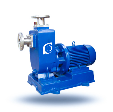
Product Overview
X / ZXL Clean Water Self-Priming Centrifugal Pump is a single-stage self-priming centrifugal pump designed for clean water and low-viscosity fluid transfer where suction lift is required.
It resolves suction-side priming difficulties, eliminates the need for foot valves in certain installations, and ensures reliable restart after intermittent operation.
It is applied in irrigation systems, industrial water transfer, municipal drainage, and temporary pumping stations where suction lift and easy installation are required.
Model Designation

Applications
Typical Operating Scenarios
• Irrigation systems with negative suction head and above-ground pump installation
• Industrial cooling water circulation where intermittent restart is required
• Municipal drainage pits with limited priming accessibility
• Temporary water transfer stations without foot valve configuration
• Construction site water removal with short-distance suction lift
Engineering Advantages
Structural Logic & Engineering Outcome
• Enlarged self-priming chamber design ensures rapid air-water separation and stable suction lift performance
• Single-stage radial impeller optimized for clean water hydraulic efficiency
• Compact horizontal structure simplifies installation and maintenance
• Mechanical seal configuration reduces leakage risk under frequent start-stop conditions
System Components
X / ZXL Clean Water Self-Priming Centrifugal Pump:
• Pump casing with self-priming chamber
• Radial impeller
• Pump shaft
• Mechanical seal assembly
• Bearing housing
• Coupling
• Electric motor
Technical Data
Service Conditions
• Clean water or similar low-viscosity fluids
• No solid particles or minimal suspended impurities
Operating Conditions
Flow: 3.2 – 600 m³/h
• Head: 12 – 80 m
• Power: 0.75 – 132 kW
• Suction Lift: 5 – 6.5 m (per outlet diameter)
Detailed parameter tables are provided below.
Installation & Dimensions
Outline Drawing

Performance Data
| 1 | Coupling | 2 | Pump Shaft | 3 | Bearing | 4 | Mechanical Seal | 5 | Bearing Housing | 6 | Pump Casing | 7 | Discharge Base |
| 8 | Suction Base | 9 | Front Seal Ring | 10 | Impeller | 11 | Rear Cover | 12 | Water Deflector Ring | 13 | Filling Port | 14 | Return Port |
Performance Parameters
| Model |
Inlet
|
Outlet
|
Suction Lift
|
Motor Power
|
Flow Rate
|
Head
|
| (mm) | (mm) | (m) | (kW) | (m3/h) | (m) | |
| 25ZXL3.2-20 | 25 | 25 | 6.5 | 0.75 | 3.2 | 20 |
| 25ZXL3.2-32 | 25 | 25 | 6.5 | 1.1 | 3.2 | 32 |
| 40ZXL6.3-20 | 40 | 32 | 6.5 | 1.1 | 6.3 | 20 |
| 40ZXL10-40 | 40 | 40 | 6.5 | 4 | 10 | 40 |
| 50ZXL15-12 | 50 | 50 | 6.5 | 1.5 | 15 | 12 |
| 50ZXL18-20 | 50 | 50 | 6.5 | 2.2 | 18 | 20 |
| 50ZXL12.5-32 | 50 | 50 | 6.5 | 3 | 12.5 | 32 |
| 50ZXL20-30 | 50 | 50 | 6.5 | 4 | 20 | 30 |
| 50ZXL14-35 | 50 | 50 | 6.5 | 4 | 14 | 35 |
| 50ZXL10-40 | 50 | 50 | 6.5 | 4 | 10 | 40 |
| 50ZXL12.5-50 | 50 | 50 | 6.5 | 5.5 | 12.5 | 50 |
| 50ZXL15-60 | 50 | 50 | 6.5 | 7.5 | 15 | 60 |
| 50ZXL20-75 | 50 | 50 | 6.5 | 11 | 20 | 75 |
| Model |
Inlet
|
Outlet
|
Suction Lift
|
Motor Power
|
Flow Rate
|
Head
|
| (mm) | (mm) | (m) | (kW) | (m3/h) | (m) | |
| 65ZXL30-15 | 65 | 50 | 6.5 | 3 | 30 | 15 |
| 65ZXL25-32 | 65 | 50 | 6 | 5.5 | 25 | 32 |
| 80ZXL35-13 | 80 | 80 | 6 | 2.2 | 35 | 13 |
| 80ZXL43-17 | 80 | 80 | 6 | 4 | 43 | 17 |
| 80ZXL40-22 | 80 | 80 | 6 | 5.5 | 40 | 22 |
| 80ZXL50-25 | 80 | 80 | 6 | 7.5 | 50 | 25 |
| 80ZXL50-32 | 80 | 80 | 6 | 7.5 | 50 | 32 |
| 80ZXL60-55 | 80 | 80 | 6 | 18.5 | 60 | 55 |
| 80ZXL60-70 | 80 | 80 | 6 | 22 | 60 | 70 |
| 100ZXL100-20 | 100 | 80 | 6 | 11 | 100 | 20 |
| 100ZXL100-40 | 100 | 100 | 6 | 18.5 | 100 | 40 |
| 100ZXL100-65 | 100 | 100 | 6 | 30 | 100 | 65 |
| 100ZXL70-75 | 100 | 100 | 6 | 30 | 70 | 75 |
| Model |
Inlet
|
Outlet
|
Suction Lift
|
Motor Power
|
Flow Rate
|
Head
|
| (mm) | (mm) | (m) | (kW) | (m3/h) | (m) | |
| 150ZXL170-55 | 150 | 150 | 5 | 45 | 170 | 55 |
| 150ZXL170-65 | 150 | 150 | 5 | 55 | 170 | 65 |
| 150ZXL160-80 | 150 | 150 | 5 | 55 | 160 | 80 |
| 200ZXL400-32 | 200 | 200 | 5 | 55 | 400 | 32 |
| 200ZXL280-63 | 200 | 200 | 5 | 90 | 280 | 63 |
| 200ZXL350-65 | 200 | 200 | 5 | 110 | 350 | 65 |
| 250ZXL550-32 | 250 | 250 | 5 | 75 | 550 | 32 |
| 250ZXL400-50 | 250 | 250 | 5 | 90 | 400 | 50 |
| 250ZXL450-55 | 250 | 250 | 5 | 110 | 450 | 55 |
| 250ZXL400-75 | 250 | 250 | 5 | 132 | 400 | 75 |
| 300ZXL600-32 | 300 | 300 | 5 | 90 | 600 | 32 |
| 300ZXL500-50 | 300 | 300 | 5 | 110 | 500 | 50 |
| 300ZXL550-55 | 300 | 300 | 5 | 132 | 550 | 55 |
How to Select a Pump Model
• Determine required suction lift height and confirm self-priming capability margin
• Calculate duty point (flow rate & head) based on pipeline loss and elevation difference
• Confirm restart frequency and select suitable seal configuration
• Evaluate installation layout to ensure proper suction piping design
• Verify liquid temperature and medium cleanliness level
Engineering Notes
• Self-priming height is influenced by suction pipe length and leakage tightness
• Avoid excessive suction pipeline resistance
• Installation base must ensure alignment stability
• Not suitable for fluids with large solids or fibrous content
Compliance & Quality Assurance
• Hydraulic performance test according to design duty point
• Casing hydrostatic pressure test
• Dynamic balance verification of impeller
• Material traceability documentation
• Optional third-party inspection upon request
Safety Notice
• Do not operate under dry-running condition
• Ensure suction piping is airtight before startup
• Disconnect power before maintenance
• Do not exceed specified temperature and pressure limits
OEM & Customization
This pump series supports engineered configuration and duty-based matching. Technical adjustments can be made according to system requirements and installation conditions.
Available options include:
• Motor voltage & frequency
• Mechanical seal type and configuration
• Wetted parts material selection
• Surface coating and corrosion protection
Configuration is determined based on duty point and project specifications.
FAQs
Q: What is the maximum self-priming height?
A: Self-priming height depends on model and suction pipeline configuration, typically up to 6–8 meters under standard conditions.
Q: Can the pump operate under VFD control?
A: Yes, operation under variable frequency drive is possible within rated speed limits.
Q: What sealing options are available?
A: Standard mechanical seal, with optional high-temperature or corrosion-resistant configurations.
Q: What is the allowable working pressure?
A: Maximum working pressure is ≤ 1.0 MPa depending on model.
Q: Is the pump suitable for slightly contaminated water?
A: Limited suspended particles are acceptable; not suitable for heavy solids or fibrous media.
Q: What standards does the pump comply with?
A: Designed according to general centrifugal pump structural standards and internal factory performance validation procedures.