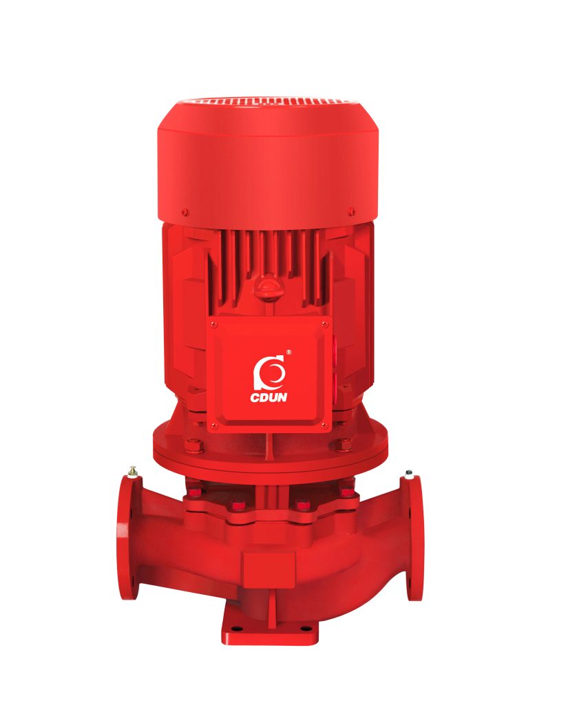
Product Overview
XBD-HY Vertical Single-Stage Fire Pump is a vertical, single-stage centrifugal fire pump driven by electric motor, designed for fixed fire protection water supply systems requiring stable rated flow and pressure under emergency conditions.
It addresses the engineering requirement of maintaining constant discharge pressure and rapid response start-up in sprinkler and hydrant systems.
It is applied in high-rise buildings, commercial complexes, industrial plants, warehouses, and municipal fire networks.
Model Designation

Applications
- Fire hydrant networks with fixed discharge pressure requirement
- Automatic sprinkler systems requiring immediate pressure rise
- High-rise building fire water booster rooms
- Industrial workshop fire pipeline circulation
- Municipal auxiliary fire water supply stations
Engineering Advantages
Vertical in-line structure minimizes footprint and ensures coaxial inlet/outlet alignment, reducing hydraulic loss and pipeline stress.
Single-stage optimized impeller provides stable rated head under fire duty condition.
Rigid shaft support and precision balancing ensure low vibration during emergency continuous operation.
Motor direct coupling design reduces transmission loss and improves reliability.
Original engineering summary integrated: Designed in accordance with fire system hydraulic standards to ensure rated performance under emergency start conditions.
System Components
XBD-HY Vertical Single-Stage Fire Pump:
- Pump casing (volute type)
- Closed single-stage impeller
- Pump shaft and bearing assembly
- Mechanical seal or packing seal
- Electric motor (fire rated)
- Base frame and coupling system
Technical Data
Service Conditions
Clean water without solid particles, suitable for fire protection systems.
Operating Conditions
Flow Rate: 3.6 – 18 m³/h
Head: 30 – 113 m
Power Range: 1.5 – 30 kW
Speed: 2850 rpm
Liquid Temperature: ≤ 80°C
Working Pressure: ≤ 1.6 MPa
Detailed parameter tables are provided below.
Installation & Dimensions
Outline Drawing

Performance Data
| No. | Name | No. | Name |
| 1 | Pump Body | 6 | Pump Cover |
| 2 | Impeller | 7 | Mechanical Seal |
| 3 | Impeller Nut | 8 | Water Deflector Ring |
| 4 | Air Release Valve | 9 | Motor |
| 5 | Plug |
Performance
| Item No. | Product Model | Diameter | Rated Flow Rate | Rated Pressure | Rated Power | Rated Speed |
| mm | L/s | Mpa | kW | r/min | ||
| 1 | XBD3.2/1W-HY | 25 | 1 | 0.32 | 1.5 | 2850 |
| 2 | XBD3.8/1W-HY | 32 | 1 | 0.38 | 1.5 | 2850 |
| 3 | XBD4.0/1W-HY | 32 | 1 | 0.4 | 2.2 | 2850 |
| 4 | XBD4.5/1W-HY | 32 | 1 | 0.45 | 2.2 | 2850 |
| 5 | XBD5.0/1W-HY | 32 | 1 | 0.5 | 3 | 2850 |
| 6 | XBD6.0/1W-HY | 40 | 1 | 0.6 | 4 | 2850 |
| 7 | XBD7.0/1W-HY | 40 | 1 | 0.7 | 5.5 | 2850 |
| 8 | XBD8.0/1W-HY | 40 | 1 | 0.8 | 7.5 | 2850 |
| 9 | XBD3.2/1.1W-HY | 25 | 1.1 | 0.32 | 1.5 | 2850 |
| 10 | XBD3.8/1.1W-HY | 32 | 1.1 | 0.38 | 1.5 | 2850 |
| 11 | XBD4.0/1.1W-HY | 32 | 1.1 | 0.4 | 2.2 | 2850 |
| 12 | XBD4.5/1.1W-HY | 32 | 1.1 | 0.45 | 2.2 | 2850 |
| 13 | XBD5.0/1.1W-HY | 32 | 1.1 | 0.5 | 3 | 2850 |
| 14 | XBD6.0/1.1W-HY | 40 | 1.1 | 0.6 | 4 | 2850 |
| 15 | XBD7.0/1.1W-HY | 40 | 1.1 | 0.7 | 5.5 | 2850 |
| 16 | XBD8.0/1.1W-HY | 40 | 1.1 | 0.8 | 7.5 | 2850 |
| 17 | XBD3.2/1.5W-HY | 40 | 1.5 | 0.32 | 2.2 | 2850 |
| 18 | XBD4.4/1.5W-HY | 40 | 1.5 | 0.44 | 3 | 2850 |
| 19 | XBD5.0/1.5W-HY | 40 | 1.5 | 0.5 | 4 | 2850 |
| 20 | XBD6.0/1.5W-HY | 40 | 1.5 | 0.6 | 4 | 2850 |
| 21 | XBD7.0/1.5W-HY | 40 | 1.5 | 0.7 | 5.5 | 2850 |
| 22 | XBD8.0/1.5W-HY | 40 | 1.5 | 0.8 | 7.5 | 2850 |
| 23 | XBD3.0/2W-HY | 40 | 2 | 0.3 | 2.2 | 2850 |
| 24 | XBD4.2/2W-HY | 40 | 2 | 0.42 | 3 | 2850 |
| 25 | XBD4.8/2W-HY | 40 | 2 | 0.48 | 4 | 2850 |
| 26 | XBD5.8/2W-HY | 40 | 2 | 0.58 | 4 | 2850 |
| 27 | XBD6.8/2W-HY | 40 | 2 | 0.68 | 5.5 | 2850 |
| 28 | XBD7.8/2W-HY | 40 | 2 | 0.78 | 7.5 | 2850 |
| 29 | XBD3.5/3W-HY | 50 | 3 | 0.35 | 3 | 2850 |
| 30 | XBD4.4/3W-HY | 50 | 3 | 0.44 | 4 | 2850 |
| 31 | XBD5.0/3W-HY | 50 | 3 | 0.5 | 5.5 | 2850 |
| 32 | XBD5.8/3W-HY | 50 | 3 | 0.58 | 7.5 | 2850 |
| 33 | XBD6.8/3W-HY | 50 | 3 | 0.68 | 7.5 | 2850 |
| 34 | XBD7.8/3W-HY | 50 | 3 | 0.78 | 11 | 2850 |
| 35 | XBD4.3/4W-HY | 50 | 4 | 0.43 | 4 | 2850 |
| 36 | XBD4.9/4W-HY | 50 | 4 | 0.49 | 5.5 | 2850 |
| 37 | XBD5.6/4W-HY | 50 | 4 | 0.56 | 7.5 | 2850 |
| 38 | XBD6.6/4W-HY | 50 | 4 | 0.66 | 7.5 | 2850 |
| 39 | XBD11.3/4W-HY | 50 | 4 | 1.13 | 30 | 2850 |
| 40 | XBD3.2/5W-HY | 50 | 5 | 0.32 | 4 | 2850 |
| 41 | XBD4.5/5W-HY | 50 | 5 | 0.45 | 5.5 | 2850 |
| 42 | XBD5.0/5W-HY | 50 | 5 | 0.5 | 7.5 | 2850 |
| 43 | XBD5.8/5W-HY | 50 | 5 | 0.58 | 7.5 | 2850 |
| 44 | XBD7.0/5W-HY | 50 | 5 | 0.7 | 11 | 2850 |
| 45 | XBD7.8/5W-HY | 50 | 5 | 0.78 | 15 | 2850 |
| 46 | XBD8.5/5W-HY | 50 | 5 | 0.85 | 18.5 | 2850 |
| 47 | XBD9.5/5W-HY | 50 | 5 | 0.95 | 18.5 | 2850 |
| 48 | XBD10.0/5W-HY | 50 | 5 | 1 | 18.5 | 2850 |
| 49 | XBD10.5/5W-HY | 50 | 5 | 1.05 | 22 | 2850 |
| 50 | XBD11.2/5W-HY | 50 | 5 | 1.12 | 30 | 2850 |
Installation Diagram
|
|
|||||||||||||||||||||||||||||||||||||||||||||||||||||||||||||||||||||||||

Installation Diagram(2)
|
|
|||||||||||||||||||||||||||||||||||||||||||||||||||||||||||||||||||||||||


Performance Data(2)
| Motor Power | Bearing | Mechanical Seal |
|
0.18KW、0.12KW
|
201 | 104-12 |
|
0.25KW、0.37KW
|
202 | 104-14 |
|
0.55KW、0.75KW、1.1KW-2
|
204 | 109-18 |
|
1.1KW-4、 1.5KW、2.2KW-2
|
205 | 109-20 |
|
2.2KW-4、3KW
|
206 | 109-25 |
| 4KW | 306 | 109-25 |
| 5.5KW、7.5KW-2、7.5KW-4 | 308 | 109-25 |
|
11KW、15KW、 18.5KW-2、22KW-2
|
309 | 109-35 |
|
18.5KW-4、22KW-4
|
311 | 109-45 |
| 30KW、37KW-2 | 312 | 109-45 |
| 37KW-4、45KW | 313 | 109-45 |
| 55KW、75KW-2、90KW-2 | 314 | 109-55 |
Performance Parameters
| Pipe Diameter (mm) | Flow Rate (L/s) | |||||||||||||||||||||||
| 1 | 2 | 4 | 6 | 8 | 10 | |||||||||||||||||||
| 25 | 3.2 | 13 | ||||||||||||||||||||||
| 38 | 3.5 | 14 | 15 | 15 | 20 | |||||||||||||||||||
| 50 | 0.8 | 3.1 | 13 | 29 | 25 | 30 | ||||||||||||||||||
| 65 | 0.8 | 3.2 | 7.1 | 13 | 20 | 40 | 50 | |||||||||||||||||
| 75 | 0.4 | 1.6 | 3.3 | 5.9 | 9.6 | 21.6 | 60 | 70 | ||||||||||||||||
| 100 | 0.4 | 0.8 | 1.3 | 2.1 | 6.8 | 8.6 | 13 | 19. | 80 | 90 | ||||||||||||||
| 125 | 0.2 | 0.4 | 0.6 | 1.3 | 2.7 | 4.1 | 5.9 | 10. | 100 | 110 | ||||||||||||||
| 150 | 0.1 | 0.2 | 0.5 | 1.1 | 1.6 | 2.3 | 4.2 | 6.4 | 9.4 | 120 | 130 | |||||||||||||
| 175 | 0.1 | 0.2 | 0.5 | 0.7 | 1.0 | 1.9 | 2.9 | 4.3 | 5.8 | 7.7 | 9.6 | 140 | 160 | |||||||||||
| 200 | 0.1 | 0.2 | 0.3 | 0.5 | 0.9 | 1.5 | 2.1 | 2.9 | 3.7 | 4.7 | 6.1 | 7.2 | 8.5 | 180 | 200 | |||||||||
| 250 | 0.1 | 0.1 | 0.2 | 0.3 | 0.5 | 0.7 | 0.9 | 1.2 | 1.5 | 1.9 | 2.3 | 2.8 | 3.3 | 3.7 | 4.9 | 5.2 | ||||||||
| 300 | 0.1 | 0.1 | 0.2 | 0.3 | 0.4 | 0.5 | 0.6 | 0.7 | 0.9 | 1.1 | 1.3 | 1.5 | 2.0 | 2.4 | 3.0 | |||||||||
Pipe Flow and Length
| Type | Equivalent Length (Multiples of Pipe Diameter) | Remarks |
| Fully Open Gate Valve | 12 | Double the value if not fully open |
| Standard Elbow | 25 | |
| Check Valve | 100 | |
| Foot Valve | 100 | Double the value if partially clogged |
Pipe Diameter and Flow
|
|
H2 How to Select a Pump Model
Select based on required rated fire flow and system design pressure.
Confirm pump curve meets fire code duty point at rated speed.
Verify motor power margin under full load operation.
Check allowable working pressure versus pipeline rating.
Consider installation space and vertical alignment requirements.
Engineering Notes
Designed for emergency fire activation; not intended for continuous process boosting.
Pump performance must comply with local fire hydraulic standards.
Vertical configuration reduces floor load concentration.
Suitable for integration with fire control panels and pressure controllers.
Compliance & Quality Assurance
• Hydraulic performance test according to rated fire duty
• Pressure casing hydrostatic test
• Impeller dynamic balance verification
• Motor insulation and protection class verification
• Material traceability documentation
Safety Notice
• Do not operate without water filling.
• Ensure system priming before emergency start.
• Verify rotational direction before commissioning.
• Disconnect power before maintenance.
OEM & Customization
This pump series supports engineered configuration and duty-based matching. Technical adjustments can be made according to system requirements and installation conditions.
Available options include:
• Motor voltage & frequency
• Mechanical seal type and configuration
• Wetted parts material selection
• Surface coating and corrosion protection
Configuration is determined based on duty point and project specifications.
Based on duty point and project specifications.
H2 FAQs
Q: Can the pump operate under VFD control?
A: Fire pumps are typically operated at rated speed; VFD use must comply with fire code regulations.
Q: What is the allowable working pressure?
A: Maximum working pressure is 1.6 MPa as per casing design.
Q: What sealing options are available?
A: Mechanical seal or packing seal depending on fire system specification.
Q: What standards does the pump comply with?
A: Designed to meet hydraulic requirements of fixed fire protection systems.
Q: What is the rated speed?
A: Standard configuration is 2900 rpm for 50Hz systems.
Q: Is parallel pump operation supported?
A: Yes, parallel configuration can be applied for higher system flow demand.