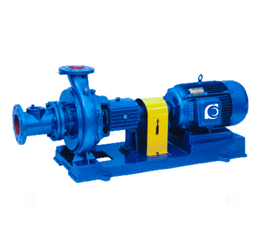
Product Overview
XWJ Series Non-Clogging Pulp Pump is a horizontal single-stage centrifugal pulp pump designed for continuous conveying of fiber-containing paper pulp and light-industry slurry.
It addresses fiber entanglement, clogging, and hydraulic instability commonly encountered in medium- and low-consistency pulp transport systems.
It is suitable for paper stock preparation, pulp circulation systems, recycled fiber processing lines, and light-industry slurry conveying applications.
Model Designation

Applications
- Paper pulp circulation in stock preparation systems
- Medium and low consistency pulp transfer
- Pulp chest to screening or refining equipment feeding
- Recycled fiber slurry transport pipelines
- Light-industry fiber slurry conveying systems
Engineering Advantages
- Open or semi-open impeller design reduces fiber wrapping
- Enlarged flow passages enhance anti-clog capability
- Optimized hydraulic profile maintains stable head under slurry load
- Reinforced shaft and bearing support improve continuous-duty reliability
- Adjustable impeller clearance compensates for wear
System Components
XWJ Series Non-Clogging Pulp Pump:
The XWJ Series Non-Clogging Pulp Pump mainly consists of:
- Pump casing
- Open / semi-open impeller
- Pump shaft
- Shaft sleeve
- Bearing housing
- Mechanical seal or packing seal
- Coupling assembly
- Electric motor
Technical Specifications
Service Conditions
- Medium: Paper pulp or fiber-containing slurry
- Pulp consistency: ≤ 6% (depending on configuration)
- Solid fiber length must be compatible with impeller design
Operating Conditions
- Flow rate: 20–400 m³/h
- Head: 10–32 m
- Power range: 1.5–55 kW
- Speed: 1450 rpm
- Liquid temperature: ≤ 80°C
- Working pressure: ≤ 1.6 MPa
Detailed parameter tables are provided below.
Installation & Dimensions
Outline Drawing
 |
Performance Data
| 1 | Pump Body | 7 | Hose Connector |
| 2 | Adjusting Screw | 8 | Packing or Mechanical Seal |
| 3 | Wear Plate | 9 | Support Components |
| 4 | Impeller | 10 | Bracket |
| 5 | O-ring | 11 | Water Deflector Ring |
| 6 | Pump Cover | 12 | Impeller Nut |
Performance Parameters
| Model | Flow Rate (m³/h)) | Head (m) | Speed (rpm) | Matching Motor Model and Power (kW) |
| 80XWJ25-12.5 | 25 | 12.5 | 1450 | Y100L1-4/2.2 |
| 80XWJ25-12.5A | 20 | 10 | 1450 | Y90l-4/1.5 |
| 80XWJ25-20 | 25 | 20 | 1450 | Y100L2-4/3 |
| 80XWJ25-20A | 20 | 16 | 1450 | Y100L-4/2.2 |
| 100XWJ50-20 | 50 | 20 | 1450 | Y132S-4/5.5 |
| 100XWJ50-20A | 45 | 18 | 1450 | Y112M-4/4 |
| 100XWJ50-20B | 40 | 16 | 1450 | Y112M-4/4 |
| 100XWJ50-32 | 50 | 32 | 1450 | Y160M-4/11 |
| 100XWJ50-32A | 40 | 26 | 1450 | Y132S-4/5.5 |
| 125XWJ100-20 | 100 | 20 | 1450 | Y160M-4/11 |
| 125XWJ100-20A | 90 | 18 | 1450 | Y132S-4/7.5 |
| 125XWJ100-20B | 80 | 16 | 1450 | Y132S-4/7.5 |
| 125XWJ100-32 | 100 | 32 | 1450 | Y160M-4/15 |
| 125XWJ100-32A | 90 | 28 | 1450 | Y160M-4/11 |
| 125XWJ100-32B | 80 | 26 | 1450 | Y160M-4/11 |
| 150XWJ200-20 | 200 | 20 | 1450 | Y180M-4/18.5 |
| 150XWJ200-20A | 180 | 18 | 1450 | Y160M-4/15 |
| 150XWJ200-20B | 160 | 16 | 1450 | Y160M-4/11 |
| 150XWJ200-32 | 200 | 32 | 1450 | Y200L-4/30 |
| 150XWJ200-32A | 187 | 28 | 1450 | Y180M-4/22 |
| 150XWJ200-32B | 170 | 24 | 1450 | Y180M-4/18.5 |
| 200XWJ400-20 | 400 | 20 | 1450 | Y225S-4/37 |
| 200XWJ400-20A | 380 | 18 | 1450 | Y200L-4/30 |
| 200XWJ400-20B | 340 | 15 | 1450 | Y180L-4/22 |
| 200XWJ400-32 | 400 | 32 | 1450 | Y250M-4/55 |
| 200XWJ400-32A | 375 | 28 | 1450 | Y225M-4/45 |
| 200XWJ400-32B | 340 | 24 | 1450 | Y225S-4/37 |
| Note: The test medium is clean water at normal temperature. | ||||
Performance Curves

How to Select a Pump Model
- Determine pulp consistency and fiber characteristics
- Confirm required flow rate and total dynamic head
- Evaluate suction conditions and NPSH margin
- Select sealing configuration based on leakage tolerance and flushing requirement
- Verify motor power under continuous-duty load conditions
Engineering Notes
- Not suitable for high-abrasive mineral slurry
- Excessively long fibers may require modified impeller geometry
- Seal flushing may be required under higher pulp consistency
- Regular inspection of impeller clearance is recommended
- Bearing lubrication condition must be monitored under continuous duty
Compliance & Quality Assurance
• Factory hydraulic performance test according to rated duty point
- Hydrostatic pressure test on pump casing
- Rotor dynamic balance verification
- Seal chamber dimensional inspection
- Material certification and traceability documentation
- Optional third-party inspection available upon request
Safety Notice
- Do not operate under dry-running condition
- Ensure full priming before startup
- Do not exceed allowable pulp consistency
- Disconnect electrical power before maintenance
OEM & Customization
This pump series supports engineered configuration and duty-based matching. Technical adjustments can be made according to system requirements and installation conditions.
Available options include:
- Motor voltage & frequency
- Mechanical seal or packing type
- Wetted parts material selection
- Impeller structure modification
- Surface coating and corrosion protection
Configuration is determined based on duty point and project specifications.
FAQs
Q: What is the maximum allowable pulp consistency?
A: Typically up to 6%, depending on impeller configuration and fiber characteristics.
Q: Can the pump operate under VFD control?
A: Yes, variable frequency operation is permissible within hydraulic limits.
Q: What sealing options are available?
A: Mechanical seal or packing seal configurations are available based on process requirements.
Q: Is the pump suitable for abrasive mineral slurry?
A: No, it is designed for fiber-containing pulp rather than mineral slurry.
Q: What is the allowable working pressure?
A: Maximum working pressure is 1.6 MPa.
Q: How is clogging minimized?
A: Through enlarged flow passages and open or semi-open impeller design.
Q: Can impeller clearance be adjusted?
A: Yes, certain models allow adjustment to maintain efficiency under wear conditions.