Product Overview
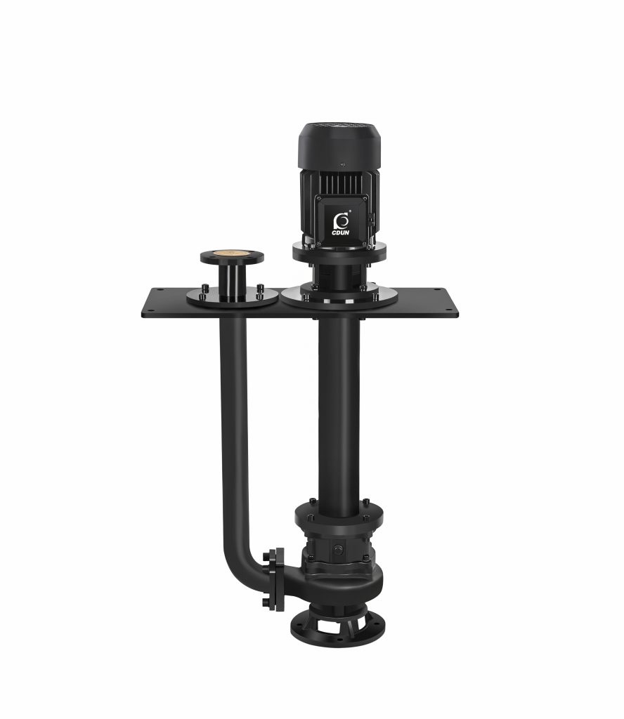
YW Series Submerged Sewage Pump is a vertical, non-clog, submerged installation sewage pump designed for continuous drainage of wastewater containing suspended solids and soft fibers in industrial and municipal systems.
It addresses clogging risk, installation space limitation, and unstable sewage discharge in confined sump or pit environments.
It is suitable for underground drainage pits, wastewater collection basins, municipal pumping stations, and industrial sewage transfer systems.
Model Designation

Applications
- Underground sump drainage with fluctuating liquid levels
- Municipal wastewater lift stations with suspended solids
- Industrial wastewater transfer containing soft fibers
- Basement flood prevention systems
- Sewage collection tanks requiring vertical submerged installation
Engineering Advantages
• Vertical submerged structure reduces footprint while ensuring hydraulic stability
• Non-clog impeller design allows passage of solids and fibrous particles
• Pump shaft supported by bearing assembly for vibration control
• Mechanical seal configuration minimizes leakage under sewage conditions
• Cast iron casing ensures structural rigidity under continuous duty
System Components
YW Series Submerged Sewage Pump:
The YW Series Submerged Sewage Pump mainly consists of:
- Pump casing
- Non-clog impeller
- Pump shaft
- Bearing assembly
- Mechanical seal
- Coupling base or support frame
- Motor
Technical Specifications
Service Conditions
- Medium: Sewage or wastewater containing suspended solids
- Installation: Vertical submerged installation
Operating Conditions
- Flow rate: 7– 2650 m³/h
- Head: 7– 35 m
- Power range: 0.55 – 250 kW
- Speed: 740/980/1450 / 2900 rpm
- Liquid temperature: ≤ 60°C
- Working pressure: ≤ 1.0 MPa
Detailed parameter tables are provided below.
Installation & Dimensions
Outline Drawing

Performance Data
| Item No. | Name | Item No. | Name |
|
1
|
Motor |
12
|
Oil Chamber |
|
2
|
Coupling |
13
|
Oil Seal |
|
3
|
Connection End Cover |
14
|
Pump Cover |
|
4
|
Bearing Press Cover |
15
|
Impeller Nut |
|
5
|
Mounting Plate |
16
|
Impeller |
|
6
|
Bearing Seat |
17
|
Discharge Elbow |
|
7
|
Bearing |
18
|
Pump Body |
|
8
|
Extended Shaft |
19
|
Wear Plate |
|
9
|
Support Tube |
20
|
Base |
|
10
|
Bearing |
21
|
Discharge Pipe |
|
11
|
Mechanical Seal |
Performance Parameters
| Model | Diameter | Flow Rate (m³/h) | Head (m) | Speed (rpm) | Power (kW) | Efficiency (%) |
| mm | (m3/h) | (M) | (r/min) | (kw) | (%) | |
| 25-7-8-0.55 | 25 | 7 | 8 | 2900 | 0.55 | 45 |
| 25-8-22-1.1 | 25 | 8 | 22 | 2900 | 1.1 | 45 |
| 32-8-12-0.75 | 32 | 8 | 12 | 2900 | 0.75 | 48 |
| 32-12-15-1.1 | 32 | 12 | 15 | 2900 | 1.1 | 45 |
| 40-15-15-1.5 | 40 | 15 | 15 | 2900 | 1.5 | 48 |
| 40-15-30-2.2 | 40 | 15 | 30 | 2900 | 2.2 | 54 |
| 50-20-7-0.75 | 50 | 20 | 7 | 2900 | 0.75 | 51 |
| 50-10-10-0.75 | 50 | 10 | 10 | 2900 | 0.75 | 52 |
| 50-20-15-1.5 | 50 | 20 | 15 | 290 | 1.5 | 53 |
| 50-15-25-2.2 | 50 | 15 | 25 | 2900 | 2.2 | 54 |
| 50-18-30-3 | 50 | 18 | 30 | 2900 | 3 | 55 |
| 50-40-15-4 | 50 | 40 | 15 | 2900 | 4 | 55 |
| 50-25-32-5.5 | 50 | 25 | 32 | 2900 | 5.5 | 55 |
| 50-20-40-7.5 | 50 | 50 | 20 | 2900 | 7.5 | 58 |
| 65-25-15-2.2 | 65 | 25 | 15 | 2900 | 2.2 | 50 |
| 65-37-13-3 | 65 | 37 | 13 | 2900 | 3 | 57 |
| 65-25-30-4 | 65 | 25 | 30 | 2900 | 4 | 61 |
| 65-30-40-7.5 | 65 | 30 | 40 | 2900 | 7.5 | 56 |
| 65-35-50-11 | 65 | 35 | 50 | 2900 | 11 | 45 |
| 65-35-60-15 | 65 | 35 | 60 | 2900 | 15 | 65 |
| 80-40-7-2.2 | 80 | 40 | 7 | 1450 | 2.2 | 59 |
| 80-43-13-3 | 80 | 43 | 13 | 2900 | 3 | 70 |
| 80-40-15-4 | 80 | 40 | 15 | 2900 | 4 | 61 |
| 80-60-13-5.5 | 80 | 60 | 13 | 2900 | 5.5 | 67 |
| 80-65-25-7.5 | 80 | 65 | 25 | 2900 | 7.5 | 63 |
| Model | Diameter | Flow Rate (m³/h) | Head (m) | Speed (rpm) | Power (kW) | Efficiency (%) |
| mm | (m3/h) | (M) | (r/min) | (kw) | (%) | |
| 100-80-10-4 | 100 | 100 | 10 | 1450 | 4 | 65 |
| 100-100-15-7.5 | 100 | 100 | 15 | 1450 | 7.5 | 68 |
| 100-80-20-7.5 | 100 | 80 | 20 | 1450 | 7.5 | 65 |
| 100-100-25-11 | 100 | 100 | 25 | 1450 | 11 | 70 |
| 100-100-30-15 | 100 | 100 | 30 | 1450 | 15 | 65 |
| 100-100-35-18.5 | 100 | 100 | 35 | 1450 | 18.5 | 68 |
| 125-130-15-11 | 125 | 130 | 15 | 1450 | 11 | 72 |
| 125-130-20-15 | 125 | 130 | 20 | 1450 | 15 | 75 |
| 150-145-9-7.5 | 150 | 145 | 9 | 1450 | 7.5 | 76 |
| 150-180-15-15 | 150 | 180 | 15 | 1450 | 15 | 69 |
| 150-180-20-18.5 | 150 | 180 | 20 | 1450 | 18.5 | 72 |
| 150-180-25-22 | 150 | 180 | 25 | 1450 | 22 | 78 |
| 150-130-30-22 | 150 | 130 | 30 | 1450 | 22 | 78 |
| 150-180-30-30 | 150 | 180 | 30 | 1450 | 30 | 78 |
| 150-200-30-37 | 150 | 200 | 30 | 1450 | 37 | 73 |
| 200-300-7-11 | 200 | 300 | 7 | 980 | 11 | 66 |
| 200-250-11-15 | 200 | 250 | 11 | 1450 | 15 | 64 |
| 200-250-15-18.5 | 200 | 250 | 15 | 1450 | 18.5 | 73 |
| 200-400-10-22 | 200 | 400 | 10 | 1450 | 22 | 75 |
| 200-400-13-30 | 200 | 400 | 13 | 14501 | 30 | 76 |
| 200-300-15-22 | 200 | 300 | 15 | 1450 | 22 | 76 |
| 200-250-22-30 | 200 | 250 | 22 | 1450 | 30 | 71 |
| 200-350-25-37 | 200 | 350 | 25 | 1450 | 37 | 71 |
| 200-400-30-45 | 200 | 400 | 30 | 1450 | 45 | 74 |
| Model | Diameter | Flow Rate (m³/h) | Head (m) | Speed (rpm) | Power (kW) | Efficiency (%) |
| mm | (m3/h) | (M) | (r/min) | (kw) | (%) | |
| 250-600-9-30 | 250 | 600 | 9 | 980 | 30 | 78 |
| 250-600-12-37 | 250 | 600 | 12 | 1450 | 37 | 76 |
| 250-600-15-45 | 250 | 600 | 15 | 1450 | 45 | 73 |
| 250-600-20-55 | 250 | 600 | 20 | 1450 | 55 | 73 |
| 250-600-25-75 | 250 | 600 | 25 | 1450 | 75 | 71 |
| 300-800-12-45 | 300 | 800 | 12 | 980 | 45 | 74 |
| 300-480-15-45 | 300 | 480 | 15 | 1450 | 45 | 66 |
| 300-800-15-55 | 300 | 800 | 15 | 1450 | 55 | 73 |
| 300-600-20-55 | 300 | 600 | 20 | 1450 | 55 | 73 |
| 300-800-20-75 | 300 | 800 | 20 | 1450 | 75 | 75 |
| 300-950-20-90 | 300 | 950 | 20 | 1450 | 90 | 76 |
| 300-1000-25-110 | 300 | 1000 | 25 | 1450 | 110 | 76 |
| 300-1100-10-55 | 300 | 1100 | 10 | 1450 | 55 | 73 |
| 350-1500-15-90 | 350 | 1500 | 15 | 740 | 90 | 87 |
| 350-1200-18-90 | 350 | 1200 | 18 | 980 | 90 | 85 |
| 350-1100-28-132 | 350 | 1100 | 28 | 980 | 132 | 84 |
| 350-1000-36-160 | 350 | 1000 | 36 | 980 | 160 | 84 |
| 400-1760-7.5-55 | 400 | 1760 | 7.5 | 980 | 55 | 83 |
| 400-1500-10-75 | 400 | 1500 | 10 | 980 | 75 | 86 |
| 400-2000-13-110 | 400 | 2000 | 13 | 980 | 110 | 84 |
| 400-2000-15-132 | 400 | 2000 | 15 | 980 | 132 | 83 |
| 400-1700-22-160 | 400 | 1700 | 22 | 980 | 160 | 83 |
| 400-1500-26-160 | 400 | 1500 | 26 | 980 | 160 | 84 |
| Model | Diameter | Flow Rate (m³/h) | Head (m) | Speed (rpm) | Power (kW) | Efficiency (%) |
| mm | (m3/h) | (M) | (r/min) | (kw) | (%) | |
| 400-1800-32-250 | 400 | 1800 | 32 | 980 | 250 | 82 |
| 500-2500-10-110 | 500 | 2500 | 10 | 740 | 110 | 85 |
| 500-2600-15-160 | 500 | 2600 | 15 | 740 | 160 | 84 |
| 500-2400-22-220 | 500 | 2400 | 22 | 740 | 220 | 85 |
| 500-2650-24-250 | 500 | 2650 | 24 | 740 | 250 | 85 |
How to Select a Pump Model
• Determine required discharge flow rate and total dynamic head
• Confirm maximum solid size and fiber content in medium
• Verify sump depth and submerged installation conditions
• Evaluate motor power based on continuous duty requirements
• Consider corrosion conditions for material compatibility
根据腐蚀环境选择材质配置
Engineering Notes
- Not suitable for liquids containing large rigid solids
- Long discharge pipelines should include check valves
- Bearing lubrication condition must be periodically inspected
- Shaft alignment must be verified during installation
- Continuous dry running is strictly prohibited
Compliance & Quality Assurance
- Factory hydraulic performance testing
- Casing hydrostatic pressure testing
- Rotor dynamic balance inspection
- Bearing clearance and vibration inspection
- Material traceability documentation
- Optional third-party inspection available
Safety Notice
- Do not operate under dry-running condition
- Ensure proper submergence level before startup
- Disconnect power before maintenance
- Do not exceed rated discharge pressure
OEM & Customization
This pump series supports engineered configuration and duty-based matching. Technical adjustments can be made according to system requirements and installation conditions.
Available options include:
- Motor voltage & frequency
- Mechanical seal type and configuration
- Wetted parts material selection
- Surface coating and corrosion protection
Configuration is determined based on duty point and project specifications.
FAQs
Q: Can the pump handle fibrous sewage media?
A: Yes, the non-clog impeller design allows passage of soft fibrous particles within rated limits.
Q: What is the allowable solid particle size?
A: Solid passage capability depends on impeller design and pump model.
Q: Can the pump operate under VFD control?
A: Yes, operation under variable frequency control is permitted within rated hydraulic limits.
Q: What sealing options are available?
A: Standard configuration includes mechanical seal; material options depend on medium conditions.
Q: What is the maximum allowable working pressure?
A: The maximum working pressure is 1.0 MPa.
Q: Is continuous operation supported?
A: Yes, the pump is designed for continuous duty under submerged conditions.
Q: What installation type is required?
A: Vertical submerged installation in sewage pits or tanks.