Product Overview
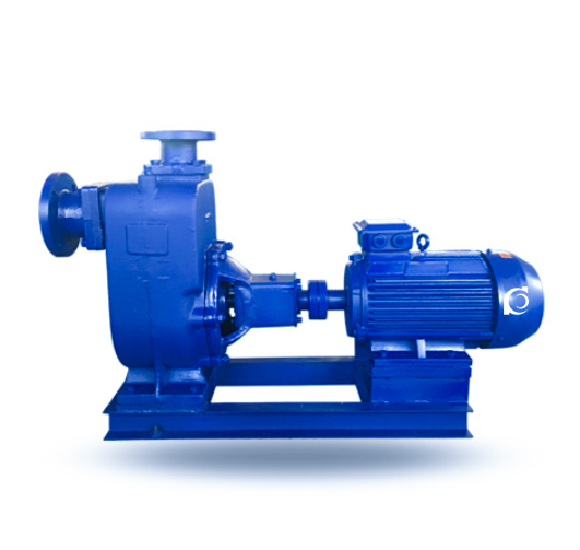
ZW / ZWL Non-Clogging Self-Priming Sewage Pump is a horizontal, non-clogging centrifugal pump with integrated self-priming structure, designed for solid-laden wastewater transfer without external priming systems.
It addresses suction limitation, frequent clogging, and complicated pipeline layouts in sewage systems requiring rapid restart and continuous drainage.
It is suitable for municipal drainage stations, industrial wastewater pits, flood control systems, and underground sump applications where dry-mounted installation is required.
Model Designation

Applications
- Underground sump drainage with intermittent inflow
- Industrial wastewater transfer containing suspended solids
- Municipal emergency flood control and stormwater pumping
- Sewage lift stations without submersible installation conditions
- Construction site dewatering with solid-laden water
Engineering Advantages
• Integrated self-priming chamber enables automatic suction without foot valve, reducing auxiliary piping complexity
• Non-clogging impeller design improves solid passage capability and reduces blockage risk
• External bearing arrangement prevents contamination from sewage media
• Mechanical seal configuration improves operational reliability under intermittent duty
• Horizontal dry-mounted structure allows convenient inspection and maintenance
System Components
ZW / ZWL Non-Clogging Self-Priming Sewage Pump mainly consists of:
- Self-priming chamber
- Pump casing
- Non-clogging impeller
- Mechanical seal assembly
- Shaft and shaft sleeve
- Bearing housing
- Suction and discharge flanges
Technical Specifications
Service Conditions
- Suitable for clean or contaminated water containing soft solids and fibers within allowable size limits.
- Installation site shall be well ventilated and protected from explosive or corrosive atmosphere.
- Ambient temperature ≤ 40°C.
Operating Conditions
- Flow rate: 8–800 m³/h
- Head: 12–80 m
- Power range: 2.2–55 kW
- Speed: 1450 / 2900 rpm
- Liquid temperature: ≤ 80°C
- Working pressure: ≤ 1.0 MPa
Detailed parameter tables are provided below.
Installation & Dimensions
Outline Drawing
 |
No.
|
Name
|
No.
|
Name
|
|
1
|
Inlet Pipe
|
9
|
Impeller
|
|
|
2
|
Inlet Flange
|
10
|
Mechanical Seal
|
|
|
3
|
Inlet Valve Seat
|
11
|
Water Ring
|
|
|
4
|
Filling Valve
|
12
|
Bearing Housing
|
|
|
5
|
Outlet Pipe
|
13
|
Pump Shaft
|
|
|
6
|
Pump Body
|
14
|
Bearing Cover
|
|
|
7
|
Air–Liquid Separation Pipe
|
15
|
Bottom Cover Plate
|
|
|
8
|
Rear Cover
|
16
|
Bolts
|
Performance Parameters
|
Model
|
Flow Rate (m³/h)
|
Head (m)
|
Motor Power (kW) |
Speed (rpm)
|
Power (kW)
|
NPSHr
|
|
(m3/h)
|
(M)
|
(kw)
|
(r/min)
|
(%)
|
(M)
|
|
|
ZW25-8-15
|
8
|
15
|
2.2
|
2900
|
45
|
2
|
|
ZW32-10-20
|
10
|
20
|
2.2
|
2900
|
45
|
2.5
|
|
ZW40-20-15
|
20
|
15
|
2.2
|
2900
|
45
|
2.5
|
|
ZW40-15-30
|
15
|
30
|
3
|
2900
|
48
|
2.5
|
|
ZW50-10-20
|
10
|
20
|
2.2
|
2900
|
45
|
2.5
|
|
ZW50-20-15
|
20
|
15
|
2.2
|
2900
|
45
|
2.5
|
|
ZW50-18-22
|
18
|
22
|
3
|
2900
|
48
|
2.5
|
|
ZW50-15-30
|
15
|
30
|
3
|
2900
|
48
|
2.5
|
|
ZW65-30-18
|
30
|
18
|
4
|
2900
|
45
|
2.5
|
|
ZW65-20-30
|
20
|
30
|
5.5
|
2900
|
45
|
2.5
|
|
ZW65-25-40
|
25
|
40
|
7.5
|
2900
|
50
|
3
|
|
ZW80-40-16
|
40
|
16
|
4
|
1450
|
50
|
3
|
|
ZW80-65-25
|
65
|
25
|
7.5
|
2900
|
50
|
3
|
|
ZW80-80-35
|
80
|
35
|
15
|
2900
|
45
|
3
|
|
ZW80-50-60
|
50
|
60
|
22
|
2900
|
55
|
3
|
|
ZW80-80-45
|
80
|
45
|
22
|
2900
|
55
|
3
|
|
Model
|
Flow Rate (m³/h)
|
Head (m)
|
Motor Power (kW)
|
Speed (rpm)
|
Power (kW)
|
NPSHr
|
|
(m3/h)
|
(M)
|
(kw)
|
(r/min)
|
(%)
|
(M)
|
|
|
ZW100-80-20
|
80
|
20
|
7.5
|
1450
|
53
|
4
|
|
ZW100-100-15
|
100
|
15
|
7.5
|
1450
|
50
|
4
|
|
ZW100-100-20
|
100
|
20
|
11
|
1450
|
53
|
4
|
|
ZW100-100-30
|
100
|
30
|
22
|
2900
|
53
|
4
|
|
ZW100-80-45
|
80
|
45
|
30
|
2900
|
55
|
4
|
|
ZW100-80-60
|
80
|
60
|
37
|
290
|
53
|
4
|
|
ZW100-80-80
|
80
|
80
|
45
|
2900
|
50
|
4
|
|
ZW125-120-20
|
120
|
20
|
15
|
1450
|
55
|
4.5
|
|
ZW150-200-15
|
200
|
15
|
15
|
1450
|
60
|
5
|
|
ZW150-200-20
|
200
|
20
|
22
|
1450
|
60
|
5
|
|
ZW150-200-28
|
200
|
28
|
30
|
1450
|
65
|
5
|
|
ZW150-400-25
|
400
|
25
|
55
|
1450
|
45
|
5
|
|
ZW150-180-40
|
180
|
40
|
55
|
1450
|
65
|
5
|
|
ZW200-280-12
|
280
|
12
|
22
|
1450
|
62
|
5
|
|
ZW200-300-18
|
300
|
18
|
37
|
1450
|
59
|
5
|
|
ZW200-300-25
|
300
|
25
|
45
|
1450
|
55
|
5
|
|
ZW200-280-28
|
280
|
28
|
55
|
1450
|
61
|
5
|
|
ZW250-400-22
|
400
|
22
|
55
|
1450
|
65
|
5
|
|
ZW300-800-14
|
800
|
14
|
55
|
1450
|
61
|
5
|
How to Select a Pump Model
• Confirm required suction lift and ensure it is within allowable self-priming range
• Determine maximum solid particle size and select proper impeller passage
• Select rotational speed (1450 rpm preferred for sewage stability)
• Evaluate duty cycle (continuous or intermittent operation)
• Confirm installation height and pipeline layout
Engineering Notes
- Not suitable for hard abrasive solids exceeding design limit
- Suction piping must remain airtight to maintain self-priming function
- Check valve is recommended to prevent reverse flow after shutdown
- Avoid excessive dry running beyond allowable priming time
Compliance & Quality Assurance
- Hydraulic performance testing before shipment
- Casing hydrostatic pressure testing
- Rotor dynamic balance inspection
- Mechanical seal integrity verification
- Material traceability documentation
Safety Notice
- Do not operate under prolonged dry-running condition
- Ensure suction line is fully sealed before startup
- Disconnect power before maintenance
- Do not exceed rated discharge pressure
OEM & Customization
This pump series supports engineered configuration and duty-based matching. Technical adjustments can be made according to system requirements and installation conditions.
Available options include:
- Motor voltage & frequency
- Mechanical seal type and configuration
- Wetted parts material selection
- Surface coating and corrosion protection
Configuration is determined based on duty point and project specifications.
FAQs
Q: Can the pump operate under VFD control?
A: Yes, within rated hydraulic limits and minimum flow requirements.
Q: What is the maximum allowable suction lift?
A: Depends on model size; refer to performance data for priming capability.
Q: What sealing options are available?
A: Standard mechanical seal; packing seal optional.
Q: What is the allowable solid size?
A: Determined by impeller passage design of each model.
Q: What rotational speeds are available?
A: 1450 rpm and 2900 rpm.
Q: Is the pump suitable for continuous operation?
A: Yes, provided suction sealing and cooling conditions are maintained.