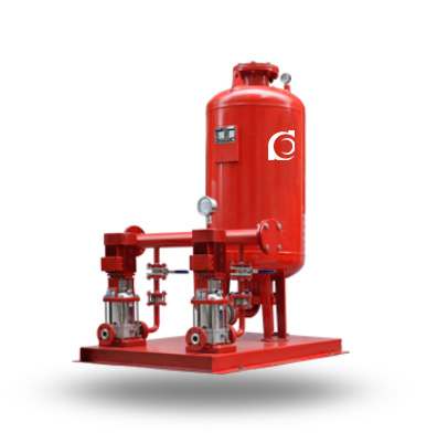
Product Overview
ZWL Fire Pressure Boosting & Stabilizing Equipment is an integrated fire water pressure maintenance system designed for hydrant and sprinkler standby applications.
It automatically maintains pipeline pressure, compensates for minor leakage, and ensures immediate system response during fire emergencies.
It is widely applied in high-rise buildings, commercial complexes, industrial plants, and dedicated fire protection water supply systems.
Model Designation

Applications
- Standby pressure maintenance for fire hydrant networks in high-rise buildings
- Pressure stabilization for automatic sprinkler systems in commercial facilities
- Fire water replenishment systems in industrial manufacturing plants
- Booster and stabilizing duty for underground fire water pipe networks
- Retrofit fire protection systems requiring automatic pressure maintenance
Engineering Advantages
- Multi-pump coordinated control maintains constant fire pipeline pressure under standby conditions.
- Automatic pressure sensing minimizes unnecessary pump cycling and reduces energy consumption.
- Compact skid-mounted construction simplifies installation and reduces plant room footprint.
- Integrated control cabinet enables automatic duty, standby, alarm, and fault switching.
- Reliable emergency startup ensures immediate fire water availability when system pressure drops.
System Components
ZWL Fire Pressure Boosting & Stabilizing Equipment mainly consists of:
- Fire jockey pump
- Standby pressure stabilizing pump
- Pressure vessel
- Pressure transmitter and gauges
- Intelligent control cabinet
- Base frame and pipeline manifold
- Valves, check valves, and accessories
Technical Specifications
Service Conditions
- Application: Fire hydrant and sprinkler pressure maintenance systems
- Medium: Clean water without solid particles
- Installation: Indoor fire pump room or dedicated equipment area
Operating Conditions
- Flow Rate: 1 – 30 m³/h
- Head: 15 – 120 m
- Power Range: 0.75 – 55 kW
- Speed: 2900 rpm
- Liquid Temperature: ≤ 80°C
- Working Pressure: ≤ 1.6 MPa
Detailed parameter tables are provided below.
Installation & Dimensions
Installation Diagram

Performance Data
|
|
|
Performance Parameters
| No. |
Booster & Pressure-Stabilizing
Unit Model |
Fire Pressure P1
(MPa) |
Vertical Diaphragm Pressure Tank | Matched Pump |
Operating Weight
(kg) |
Operating Pressure
(MPa) |
Stabilizing Water Volume (L) | ||||
| Tank Model | Working Pressure Ratio | Fire Storage Water Volume (L) | Pump Model | ||||||||
| Rated Volume | Effective Volume | ||||||||||
| 1 | ZW(L)-I-X-7 | 0.1 | SQL800*0.6 | 0.60 | 300 | 319 | 25LG3-10*4 1.5KW | 1452 |
P1=0.10 Ps1=0.26
P2=0.23 Ps2=0.31 |
54 | |
| 2 | ZW(L)-I-Z-10 | 0.16 | SQL800*0.6 | 0.80 | 150 | 159 | 25LG3-10*4 1.5KW | 1428 |
P1=0.16 Ps1=0.26
P2=0.23 Ps2=0.31 |
70 | |
| 3 | ZW(L)-I-X-10 | 0.16 | SQL800*0.6 | 0.60 | 300 | 319 | 25LG3-10*5 1.5KW | 1474 |
P1=0.16 Ps1=0.36
P2=0.33 Ps2=0.42 |
52 | |
| 4 | ZW(L)-I-X-13 | 0.22 | SQL1000*0.6 | 0.76 | 300 | 329 | 25LG3-10*4 1.5KW | 2312 |
P1=0.22 Ps1=0.35
P2=0.32 Ps2=0.40 |
97 | |
| 5 | ZW(L)-XZ-10 | 0.16 | SQL1000*0.6 | 0.65 | 450 | 480 | 25LG3-10*4 1.5KW | 2312 |
P1=0.16 Ps1=0.33
P2=0.30 Ps2=0.38 |
86 | |
| 6 | ZW(L)-XZ-13 | 0.22 | SQL1000*0.6 | 0.67 | 450 | 452 | 25LG3-10*5 1.5KW | 2312 |
P1=0.22 Ps1=0.41
P2=0.38 Ps2=0.46 |
80 | |
| 7 | ZW(L)-II-Z- | A | 0.22-0.38 | SQL800*0.6 | 0.80 | 150 | 159 | 25LG3-10*6 2.2KW | 1452 |
P1=0.38 Ps1=0.53
P2=0.50 Ps2=0.60 |
61 |
| 8 | ZW(L)-II-Z- | B | 0.38-0.50 | SQL800*1.0 | 0.80 | 150 | 159 | 25LG3-10*8 2.2KW | 1513 |
P1=0.50 Ps1=0.68
P2=0.65 Ps2=0.75 |
51 |
| 9 | ZW(L)-II-Z- | C | 0.50-0.65 | SQL1000*1.6 | 0.85 | 150 | 206 | 25LG3-10*9 2.2KW | 1653 |
P1=0.65 Ps1=0.81
P2=0.78 Ps2=0.86 |
59 |
| 10 | ZW(L)-II-Z- | D | 0.65-0.85 | SQL1000*1.6 | 0.85 | 150 | 206 | 25LG3-10*11 3KW | 1701 |
P1=0.85 Ps1=1.04
P2=1.02 Ps2=1.10 |
57 |
| 11 | ZW(L)-II-Z- | E | 0.85-1.00 | SQL1000*1.6 | 0.85 | 150 | 206 | 25LG3-10*13 4KW | 1709 |
P1=1.00 Ps1=1.21
P2=1.19 Ps2=1.27 |
50 |
| No. |
Booster & Pressure-Stabilizing
Unit Model |
Fire Pressure P1
(MPa) |
Vertical Diaphragm Pressure Tank | Matched Pump |
Operating Weight
(kg) |
Operating Pressure
(MPa) |
Stabilizing Water Volume (L) | ||||
| Tank Model | Working Pressure Ratio | Fire Storage Water Volume (L) | Pump Model | ||||||||
| Rated Volume | Effective Volume | ||||||||||
| 12 | ZW(L)-II-X- | A | 0.22-0.38 | SQL1000*0.6 | 0.78 | 300 | 302 | 25LG3-10*6 2.2KW | 2344 |
P1=0.38 Ps1=0.55
P2=0.52 Ps2=0.60 |
72 |
| 13 | ZW(L)-II-X- | B | 0.38-0.50 | SQL1000*1.0 | 0.78 | 300 | 302 | 25LG3-10*8 2.2KW | 2494 |
P1=0.50 Ps1=0.70
P2=0.67 Ps2=0.75 |
61 |
| 14 | ZW(L)-II-X- | C | 0.50-0.65 | SQL1000*1.6 | 0.78 | 300 | 302 | 25LG3-10*10 3KW | 2689 |
P1=0.65 Ps1=0.88
P2=0.86 Ps2=0.93 |
51 |
| 15 | ZW(L)-II-X- | D | 0.65-0.85 | SQL1000*1.6 | 0.85 | 300 | 355 | 25LG3-10*13 4KW | 2703 |
P1=0.85 Ps1=1.05
P2=1.02 Ps2=1.10 |
82 |
| 16 | ZW(L)-II-X- | E | 0.85-1.00 | SQL1000*1.6 | 0.88 | 300 | 355 | 25LG3-10*15 4KW | 2730 |
P1=1.00 Ps1=1.21
P2=1.19 Ps2=1.26 |
73 |
| 17 | ZW(L)-II-XZ- | A | 0.22-0.38 | SQL1200*0.6 | 0.80 | 450 | 474 | 25LG3-10*6 2.2KW | 3641 |
P1=0.38 Ps1=0.53
P2=0.50 Ps2=0.58 |
133 |
| 18 | ZW(L)-II-XZ- | B | 0.38-0.50 | SQL1200*1.0 | 0.80 | 450 | 474 | 25LG3-10*8 2.2KW | 3947 |
P1=0.50 Ps1=0.68
P2=0.65 Ps2=0.73 |
110 |
| 19 | ZW(L)-II-XZ- | C | 0.50-0.65 | SQL1200*1.6 | 0.80 | 450 | 474 | 25LG3-10*10 3KW | 3961 |
P1=0.65 Ps1=0.87
P2=0.84 Ps2=0.92 |
90 |
| 20 | ZW(L)-II-XZ- | D | 0.65-0.85 | SQL1200*1.6 | 0.80 | 450 | 474 | 25LG3-10*12 4KW | 4124 |
P1=0.85 Ps1=1.12
P2=1.09 Ps2=1.17 |
73 |
| 21 | ZW(L)-II-XZ- | E | 0.85-1.00 | SQL1200*1.6 | 0.80 | 450 | 474 | 25LG3-10*14 4KW | 4156 |
P1=1.00 Ps1=1.30
P2=1.27 Ps2=1.35 |
64 |
| Note: 1. Symbols for operating pressure in the table: P1 — Charging pressure of the pressure tank (required fire pressure) (MPa) P2 — Start pressure of the fire pump (MPa) Ps1 — Start pressure of the booster / pressure-stabilizing pump (MPa) Ps2 — Stop pressure of the booster / pressure-stabilizing pump (MPa) 2. Items No. 1–6 are Type I units, generally installed in the high-level water tank room (with the most unfavorable hydrant located below the “unit”). 3. Items No. 7–21 are Type II units, usually installed in the fire pump room or water storage tank room; the listed fire pressure range and matched pumps are for selection reference. 4. Pump models listed are those of Chaodun Pump Factory; other pumps can be selected according to the required flow rate and head. |
|||||||||||
How to Select a Pump Model
- Determine required standby pressure based on the highest fire system terminal.
- Calculate leakage compensation flow for hydrant and sprinkler pipe networks.
- Verify system static pressure and allowable pressure fluctuation range.
- Select vessel volume according to startup frequency requirements.
- Confirm duty and standby pump configuration based on project fire code.
Engineering Notes
- The system is intended for standby pressure maintenance, not primary fire pumping duty.
- Pressure vessel sizing directly affects pump startup frequency and service life.
- Dual-pump configuration is recommended for critical fire protection systems.
- Control logic should coordinate with the main fire pump control system.
- Suction piping shall ensure stable water supply under standby conditions.
Compliance & Quality Assurance
- Hydraulic performance testing for each pump set
- Pressure vessel leakage and pressure retention testing
- Electrical control panel functional verification
- Material traceability for major wetted components
- Optional third-party inspection and witness testing
Safety Notices
- Do not operate under dry-running conditions.
- Ensure system is fully primed before commissioning.
- Disconnect electrical power before maintenance.
- Verify pressure vessel pre-charge before startup.
OEM & Customization
This equipment supports engineered configuration and project-based customization. Technical modifications can be made according to fire system requirements and installation conditions.
Available options include:
- Motor voltage and frequency
- Pump configuration and standby arrangement
- Pressure vessel capacity
- Control logic and communication interface
- Surface coating and corrosion protection
Configuration is determined based on duty point and project specifications.
FAQs
Q1: Can the system operate under VFD control?
A: Yes, variable frequency control is available for precise pressure maintenance.
Q2: What is the maximum allowable working pressure?
A: Standard design pressure is up to 1.6 MPa.
Q3: What sealing options are available?
A: Mechanical seals suitable for clean water fire applications are standard.
Q4: Is dual-pump redundancy recommended?
A: Yes, dual-pump arrangements are preferred for critical fire systems.
Q5: What is the recommended pressure vessel sizing method?
A: Vessel volume should be selected based on allowable hourly starts.
Q6: Which fire protection systems is it suitable for?
A: It is suitable for hydrant, sprinkler, and combined fire systems.
Q7: Can the control panel integrate with BMS or fire alarm systems?
A: Yes, optional communication protocols and dry contacts are available.