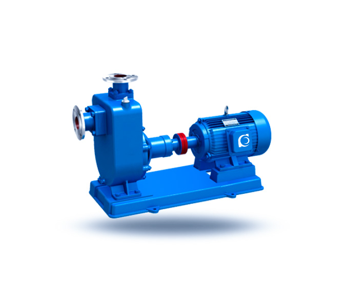
ZX / ZXL Clean Water Self-Priming Centrifugal Pump
ZX/ZXL Clean-Water Self-Priming Centrifugal Pump | Fast priming for suction-lift clean-water transfer
- Self-priming: Quick start for suction-lift installation.
- Clean-water duty: For clean water and similar low-viscosity liquids.
- Stable running: Smooth operation with controlled vibration/noise.
- Service-ready build: Compact structure with easy maintenance access.